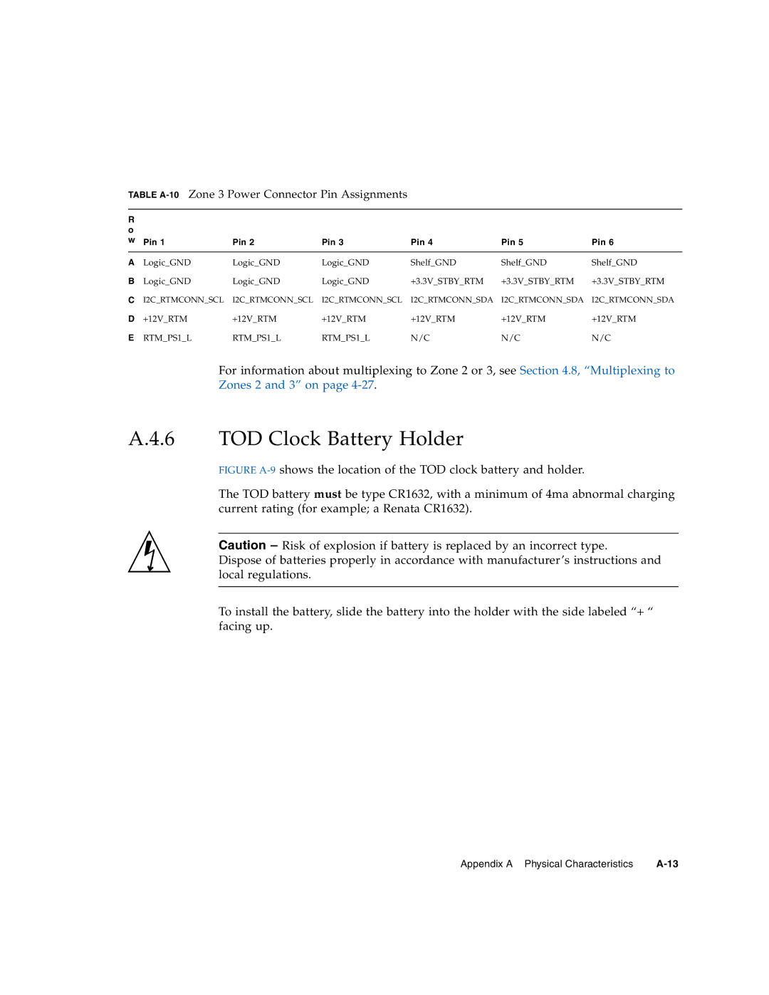
TABLE A-10 Zone 3 Power Connector Pin Assignments
R |
|
|
|
|
|
|
o |
|
|
|
|
|
|
w | Pin 1 | Pin 2 | Pin 3 | Pin 4 | Pin 5 | Pin 6 |
|
|
|
|
|
|
|
A | Logic_GND | Logic_GND | Logic_GND | Shelf_GND | Shelf_GND | Shelf_GND |
B | Logic_GND | Logic_GND | Logic_GND | +3.3V_STBY_RTM | +3.3V_STBY_RTM +3.3V_STBY_RTM | |
C I2C_RTMCONN_SCL | I2C_RTMCONN_SCL I2C_RTMCONN_SCL | I2C_RTMCONN_SDA | I2C_RTMCONN_SDA I2C_RTMCONN_SDA | |||
D +12V_RTM | +12V_RTM | +12V_RTM | +12V_RTM | +12V_RTM | +12V_RTM | |
E | RTM_PS1_L | RTM_PS1_L | RTM_PS1_L | N/C | N/C | N/C |
For information about multiplexing to Zone 2 or 3, see Section 4.8, “Multiplexing to Zones 2 and 3” on page
A.4.6 TOD Clock Battery Holder
FIGURE A-9 shows the location of the TOD clock battery and holder.
The TOD battery must be type CR1632, with a minimum of 4ma abnormal charging current rating (for example; a Renata CR1632).
Caution – Risk of explosion if battery is replaced by an incorrect type.
Dispose of batteries properly in accordance with manufacturer’s instructions and local regulations.
To install the battery, slide the battery into the holder with the side labeled “+ “ facing up.
Appendix A Physical Characteristics |
