Manuals
/
Teledyne
/
Computer Equipment
/
Computer Monitor
Teledyne
operation manual
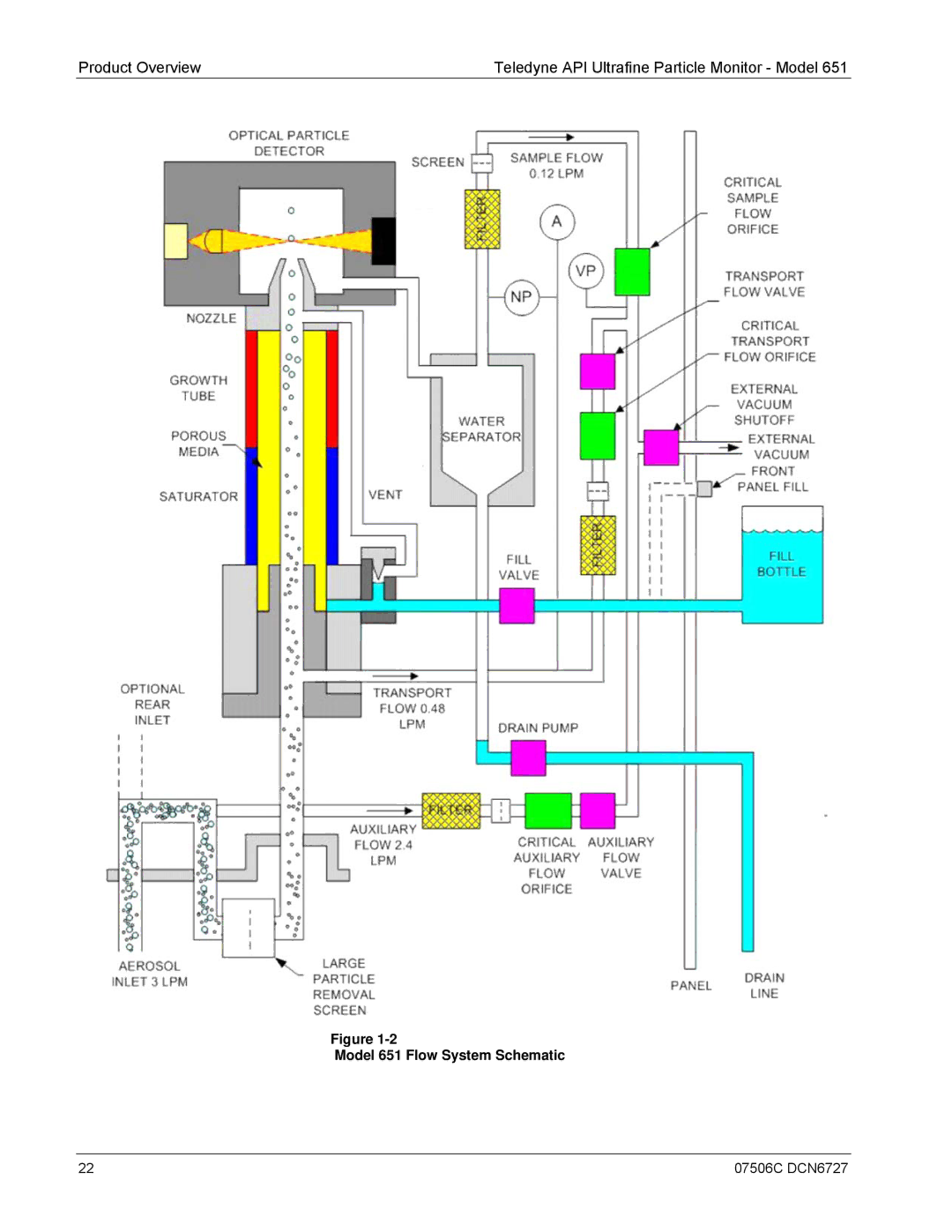
Model 651 Flow System Schematic
Models:
651
1
24
127
127
Download
127 pages
5.54 Kb
21
22
23
24
25
26
27
28
Troubleshooting
Specification
Install
Error codes
Model 651 Flow Schematic
RIE Read Instrument Errors
Connecting the Aerosol Supply
∙ Status ∙ Setup ∙ Total
Commands
Outdoor Operation Procedures
Page 24
Image 24
Product Overview
Teledyne API Ultrafine Particle Monitor - Model 651
Figure
1-2
Model 651 Flow System Schematic
22
07506C DCN6727
Page 23
Page 25
Page 24
Image 24
Page 23
Page 25
Contents
Model
Page
Trademarks
This page intentionally left blank
F e t y M e s s a g e s
Laser Safety
R N I N G
R r a n t y
This page intentionally left blank
O u t T h i s M a n u a l
V i s i o n H i s t o r y
Viii
Contents
Particle Counting
Maintenance, Service, and Troubleshooting
G u r e s
SFC Set Flow Rate Calibration Constant
B l e s
Table A-1
Xiv
How This Manual is Organized
R p o s e
G a n i z a t i o n
L a t e d P r o d u c t L i t e r a t u r e
T t i n g H e l p
Product Overview
O d u c t D e s c r i p t i o n
A P T E R
Specification s
Parameter Specification
Parameter
Water System
Physical Features
W i t W o r k s
2illustrates the flow system of the Model
Model 651 Flow System Schematic
Unpacking and Setting Up the Model
C k i n g L i s t
Model 651 Maintenance Kit PN DU0000169
P a c k i n g
Installation
Connecting the Water Supply
Equipment
Remove Protective Caps
Bracket Screw Connecting the Water Supply
Connecting the Water Exhaust Tube
Connecting the Aerosol Supply
Connecting the Aerosol Supply
Nozzle Securing Inlet Screen Assembly in Place
Installing the Model 651 in a Rack
Connecting the USB Cable
Connecting Power and Warming up the Model
Warm-up Screen
Moving and Shipping Model
Moving the Model 651 Short Distances
Preparing the Model 651 for Shipping and Storage
07506C DCN6727
Instrument Description
O n t P a n e l
Display
Indicator Light
Status Messages
C k P a n e l
T e r n a l I n s t r u m e n t C o m p o n e n t s
Optics Module
Vacuum Supply
Water System
Fans
Circuit Boards
Internal Clock
Data Communication Ports
RS-232 Serial Connections
Ethernet Communication Port
07506C DCN6727
Outdoor Operation Procedures
Instrument Operation
E r a t i n g P r e c a u t i o n s
C o m m e n d e d O p e r a t i o n P r o c e d u r e s
Standard Operation Procedures
∙ Status ∙ Setup ∙ Total
R m u p
S p l a y / U s e r S e t t i n g s
Home Screen
Status Description
Setup Screens
On After
Warmup
OFF
SET Time
Address
Total Screen
Mask
07506C DCN6727
Technical Description
E o r y
S i g n o f t h e M o d e l 6 5
Sensor
Pulse Height
Flow System
Critical Flow
Temperature Control
Inlet Pressure Measurement
Water Removal System
Page
07506C DCN6727
Particle Counting
T a l C o u n t a c c u r a c y
V e T i m e C o u n t i n g
Concentration = Total counts
N c e n t r a t i o n M e a s u r e m e n t
Concentration = N × t
07506C DCN6727
T a l i z e r M o d e
07506C DCN6727
Computer Interface Commands, and Data Collection
M p u t e r I n t e r f a c e
Ethernet
Programs and Features Choose Turn Windows features on or off
Flash Drives
Flash Memory Data Files
Line
Example of data record
USB
RS-232 Serial Communications
Terminal Communications
Communications Parameters
M m a n d s
Read
SET
07506C DCN6727
07506C DCN6727
Maintenance, Service Troubleshooting
U t i o n
M o v i n g t h e C o v e r
P l a c e m e n t P a r t s K i t s
M o v i n g a n d Install i n g t h e W i c k
T e
A n g i n g t h e F i l t e r s
R o s o l F l o w C h e c k s
Model 651 Flow Schematic
E a n i n g t h e W a t e r B o t t l e
S p e c t i n g a n d C l e a n i n g t h e F a n s
E a n / R e p l a c e t h e O r i f i c e s
S p e c t L i q u i d L i n e s
A t u s M e s s a g e s
Troubleshooting
Troubleshooting
INLET/DRAIN
C h n i c a l a s s i s t a n c e
T u r n i n g t h e M o d e l 6 5 1 f o r S e r v i c e
Primer on Electro Static Discharge
W S t a t i c C h a r g e s a r e C r e a t e d
Static Generation Voltages for Typical Activities
Sensitivity of Electronic Devices to Damage by ESD
M m o n M y t h s a b o u t E S D D a m a g e
S i c P r i n c i p l e s o f S t a t i c C o n t r o l
General Rules
07506C DCN6727
Working at the Instrument Rack
Working at an Anti-ESD Work Bench
Opening Shipments from Teledyne API’S Customer Service
Transferring Components from Rack to Bench and Back
Packing Components for Return to TAPI’s Customer Service
100 07506C DCN6727
Commands
Read SET
Command Explanation Read Commands
A D C o m m a n d s
RAI Read Analog Input Voltage
RAI
Rall Read Operating Condition
Rall
RCT Read Current Time
RD Read Displayed Concentration
RCT
RIE Read Instrument Errors
RIF Read Aerosol Flow Rate
RIE
RIF
RIS Read Instrument Status
RL Read Laser Current
RIS
RLL Read Liquid Level
RPA Read Absolute Pressure Transducer
RPN Read Nozzle Pressure Transducer
RPV Read Vacuum Pressure
RRD Read Data Record
RRD
RTA Read Cabinet Temperature
RTC Read Conditioner Temperature
RRS Read Status Record
RRS
RTG Read Growth Tube Temperature
RTO Read Optics Temperature
RV Read Firmware Version Number
SM Set Mode
T C o m m a n d s
SA Set Auxiliary Flow Valve
SFC Set Flow Rate Calibration Constant
SFC
SP Set Pump Vacuum
SR Set Real-time Clock
Sstart Starts a New Sample
Sstart
T a R e p o r t i n g R e c o r d s
ST Set Transport Flow
Record
CNT
Pstd
Record Status
Tinlet
Index
Aerosol inlet 43, 45
External vacuum source
Orifice
Teledyne Contact Information
Index-5
Top
Page
Image
Contents