Maintenance, Service, and Troubleshooting | Teledyne API Ultrafine Particle Monitor - Model 651 |
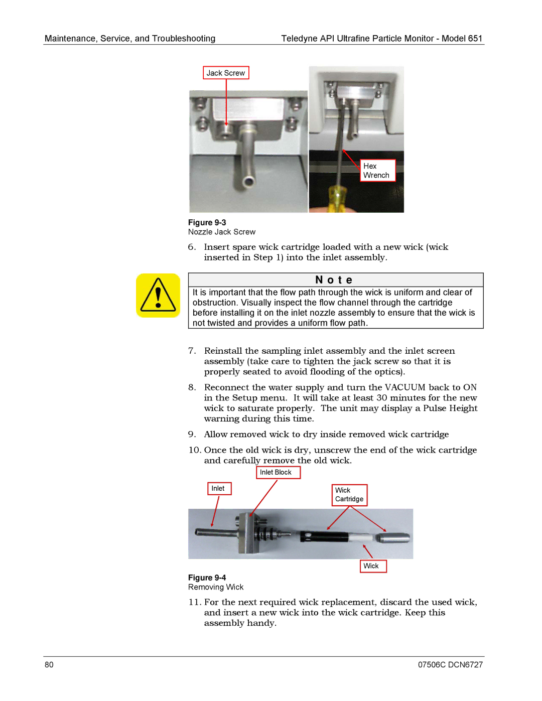
Jack Screw
![]() Hex
Hex
Wrench
Figure
Nozzle Jack Screw
6.Insert spare wick cartridge loaded with a new wick (wick inserted in Step 1) into the inlet assembly.
N o t e
It is important that the flow path through the wick is uniform and clear of obstruction. Visually inspect the flow channel through the cartridge before installing it on the inlet nozzle assembly to ensure that the wick is not twisted and provides a uniform flow path.
7.Reinstall the sampling inlet assembly and the inlet screen assembly (take care to tighten the jack screw so that it is properly seated to avoid flooding of the optics).
8.Reconnect the water supply and turn the VACUUM back to ON in the Setup menu. It will take at least 30 minutes for the new wick to saturate properly. The unit may display a Pulse Height warning during this time.
9.Allow removed wick to dry inside removed wick cartridge
10.Once the old wick is dry, unscrew the end of the wick cartridge and carefully remove the old wick.
| Inlet Block |
Inlet | Wick |
| Cartridge |
Wick
Figure
Removing Wick
11.For the next required wick replacement, discard the used wick, and insert a new wick into the wick cartridge. Keep this assembly handy.
80 | 07506C DCN6727 |