Maintenance, Service, and Troubleshooting | Teledyne API Ultrafine Particle Monitor - Model 651 |
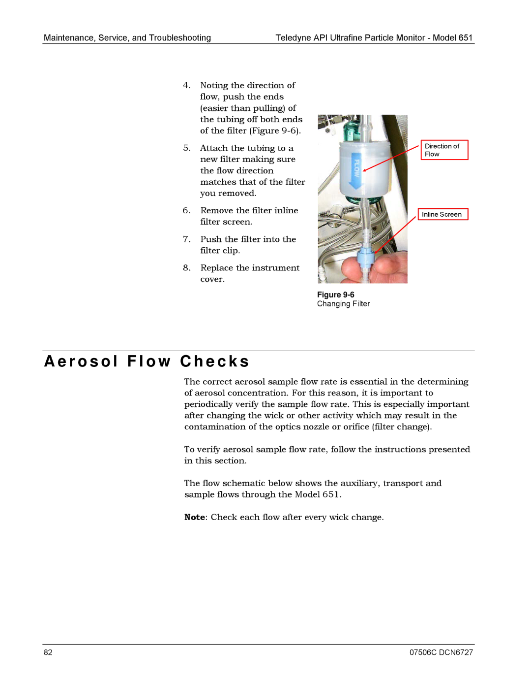
4.Noting the direction of flow, push the ends (easier than pulling) of the tubing off both ends of the filter (Figure
5.Attach the tubing to a new filter making sure the flow direction matches that of the filter you removed.
6.Remove the filter inline filter screen.
7.Push the filter into the filter clip.
8.Replace the instrument cover.
Figure
Changing Filter
Direction of Flow
Inline Screen
A e r o s o l F l o w C h e c k s
The correct aerosol sample flow rate is essential in the determining of aerosol concentration. For this reason, it is important to periodically verify the sample flow rate. This is especially important after changing the wick or other activity which may result in the contamination of the optics nozzle or orifice (filter change).
To verify aerosol sample flow rate, follow the instructions presented in this section.
The flow schematic below shows the auxiliary, transport and sample flows through the Model 651.
Note: Check each flow after every wick change.
82 | 07506C DCN6727 |