INSTALLATION PROCEDURE FOR OPTIONAL EQUIPMENT
3. Wireless LAN Module:
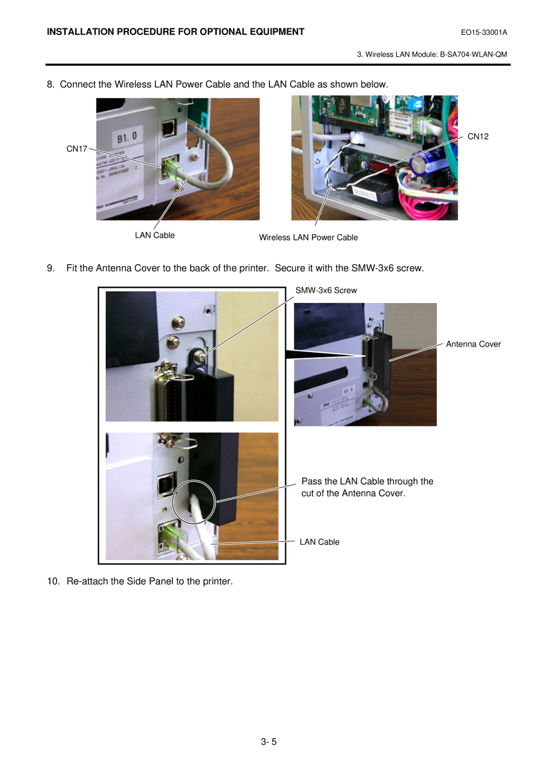
8. Connect the Wireless LAN Power Cable and the LAN Cable as shown below.
CN12
CN17
LAN Cable | Wireless LAN Power Cable |
9.Fit the Antenna Cover to the back of the printer. Secure it with the
Antenna Cover
Pass the LAN Cable through the cut of the Antenna Cover.
LAN Cable
10. Re-attach the Side Panel to the printer.
3- 5
