INSTALLATION PROCEDURE FOR OPTIONAL EQUIPMENT
(Revision Date: Jan. 19, 2006)
3. Wireless LAN Module:
3. Wireless LAN Module: B-SA704-WLAN-QM
The pictures used in this section are those of the
•Packing List
The following parts are supplied with the kit. Make sure you have all items shown below.
Wireless LAN Board (1 pc.)
Antenna Cover (1 pc.)
Installation Manual (1 copy)
Shield Sheet (1.pc)
FCC/IC Sticker (1 pc.)
NOTES:
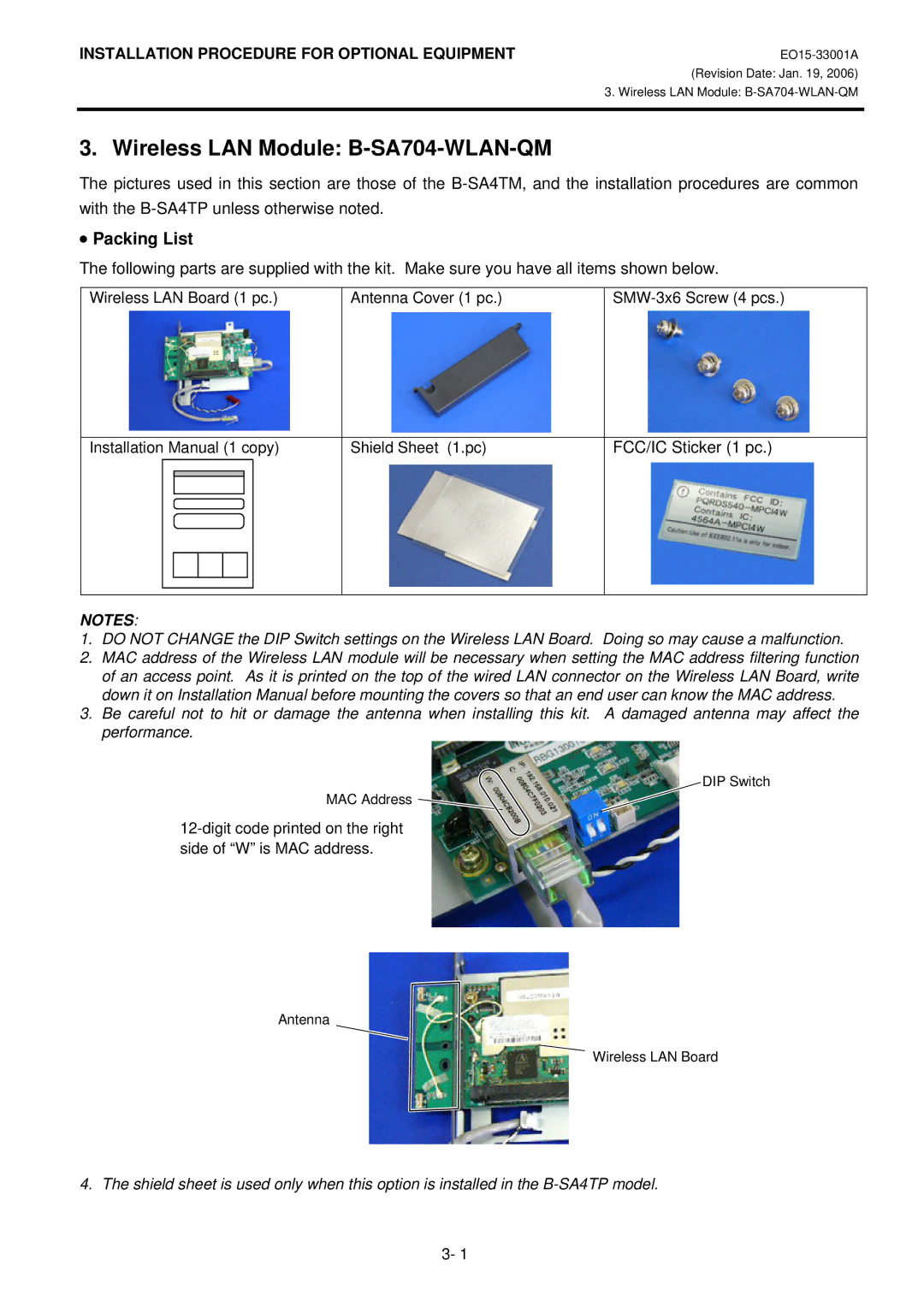
1.DO NOT CHANGE the DIP Switch settings on the Wireless LAN Board. Doing so may cause a malfunction.
2.MAC address of the Wireless LAN module will be necessary when setting the MAC address filtering function of an access point. As it is printed on the top of the wired LAN connector on the Wireless LAN Board, write down it on Installation Manual before mounting the covers so that an end user can know the MAC address.
3.Be careful not to hit or damage the antenna when installing this kit. A damaged antenna may affect the performance.
DIP Switch
MAC Address
Antenna
Wireless LAN Board
4. The shield sheet is used only when this option is installed in the
3- 1
