Toshiba B-SA4T Copper foil, Print Head Cable, Cable Clamp, SMW-3x8 Screw, Wireless LAN Module

Models: B-SA4T

1 58
Download 58 pages 37.75 Kb
Page 23
Image 23
Copper foil

INSTALLATION PROCEDURE FOR OPTIONAL EQUIPMENT

EO15-33001A

(Revision Date: Jan. 19, 2006)

3. Wireless LAN Module: B-SA704-WLAN-QM

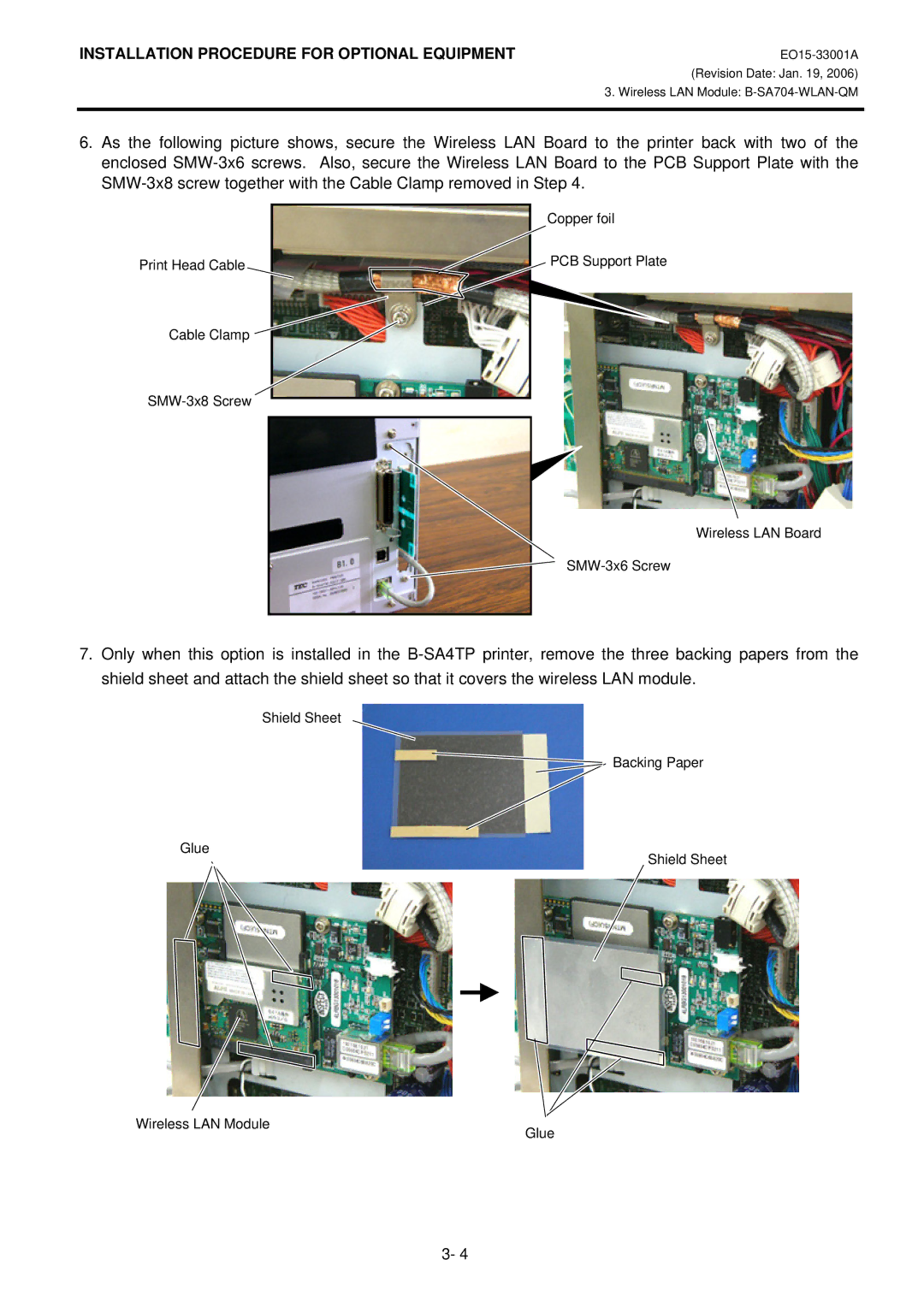
6.As the following picture shows, secure the Wireless LAN Board to the printer back with two of the enclosed SMW-3x6 screws. Also, secure the Wireless LAN Board to the PCB Support Plate with the SMW-3x8 screw together with the Cable Clamp removed in Step 4.


Copper foil

Print Head Cable

PCB Support Plate

Cable Clamp


SMW-3x8 Screw


Wireless LAN Board

SMW-3x6 Screw

7.Only when this option is installed in the B-SA4TP printer, remove the three backing papers from the shield sheet and attach the shield sheet so that it covers the wireless LAN module.

Shield Sheet

Backing Paper

Glue

Shield Sheet

Wireless LAN Module

Glue


3- 4

Page 23
Image 23
Toshiba B-SA4T Copper foil, Print Head Cable, Cable Clamp, SMW-3x8 Screw, Wireless LAN Board SMW-3x6 Screw