INSTALLATION PROCEDURE FOR OPTIONAL EQUIPMENT
(Revision Date: Jan. 19, 2006)
6. Real Time Clock:
6. Real Time Clock: B-SA704-RTC-QM-R
NOTE: When the
•Packing List
The following parts are supplied with the kit. Make sure you have all items shown below.
Real Time Clock (1 pc.) See Note. | Lithium Battery CR2032 (1 pc.) |
|
|
|
|
|
| Interface |
|
|
|
| |
|
|
|
|
|
| Cable |
|
|
|
| |
|
|
|
|
|
|
|
|
| Note: Make sure | that | the |
Installation Manual (1 copy) | Battery Sticker (1 pc.) | ||||||||||
|
|
|
|
|
|
|
|
| Interface | Cable | is |
|
|
|
|
|
|
|
|
| |||
|
|
|
|
|
|
|
|
| connected to CN1 on the | ||
|
|
|
|
|
|
|
|
| |||
|
|
|
|
|
|
|
|
| |||
|
|
|
|
|
|
|
|
| Real Time Clock. |
| |
|
|
|
|
|
|
|
|
|
| ||
|
|
|
|
|
|
|
|
|
|
|
|
|
|
|
|
|
|
|
|
|
|
|
|
|
|
|
|
|
|
|
|
|
|
|
|
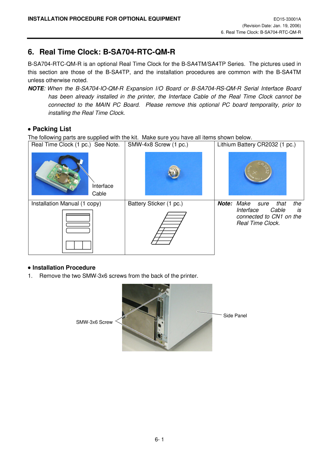
•Installation Procedure
1.Remove the two SMW-3x6 screws from the back of the printer.
![]() Side Panel
Side Panel
6- 1