INSTALLATION PROCEDURE FOR OPTIONAL EQUIPMENT
1. Cutter Module
INSTALLATION PROCEDURE FOR OPTIONAL EQUIPMENT
WARNING!
1.Turn the printer power off and disconnect the power cord before installing an optional equipment.
2.Be careful not to pinch your fingers or hands with the covers.
3.Be careful not to injure your fingers when installing the cutter module.
1.Cutter Module
1.1 B-SA204-QM / B-SA204-QM-R
CAUTION!
Do not connect/disconnect the cutter harness to/from the printer within one minute from a power off to protect the internal electrical circuit of the printer.
•Packing List
The following parts are supplied with the kit. Make sure you have all items shown below.
Cutter Unit (1 pc.)
Cutter Module Cover (1 pc.)
Installation Manual (1 copy)
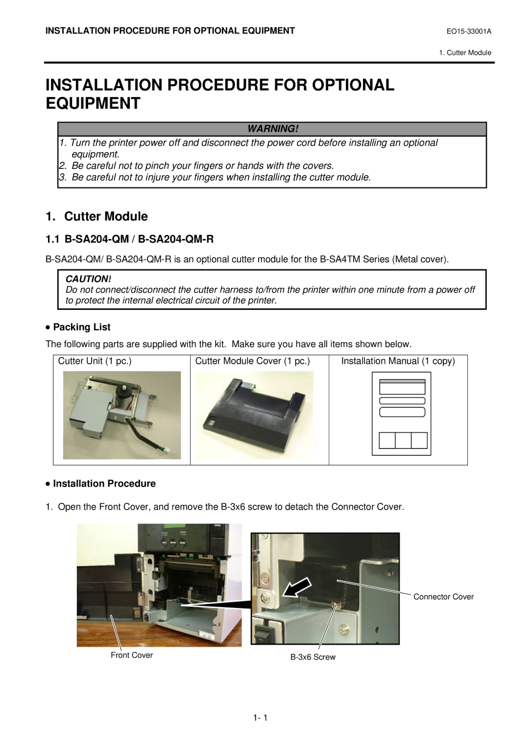
•Installation Procedure
1. Open the Front Cover, and remove the
Connector Cover
Front Cover |
1- 1