INSTALLATION PROCEDURE FOR OPTIONAL EQUIPMENT
3. Wireless LAN Module:
•Installation Procedure
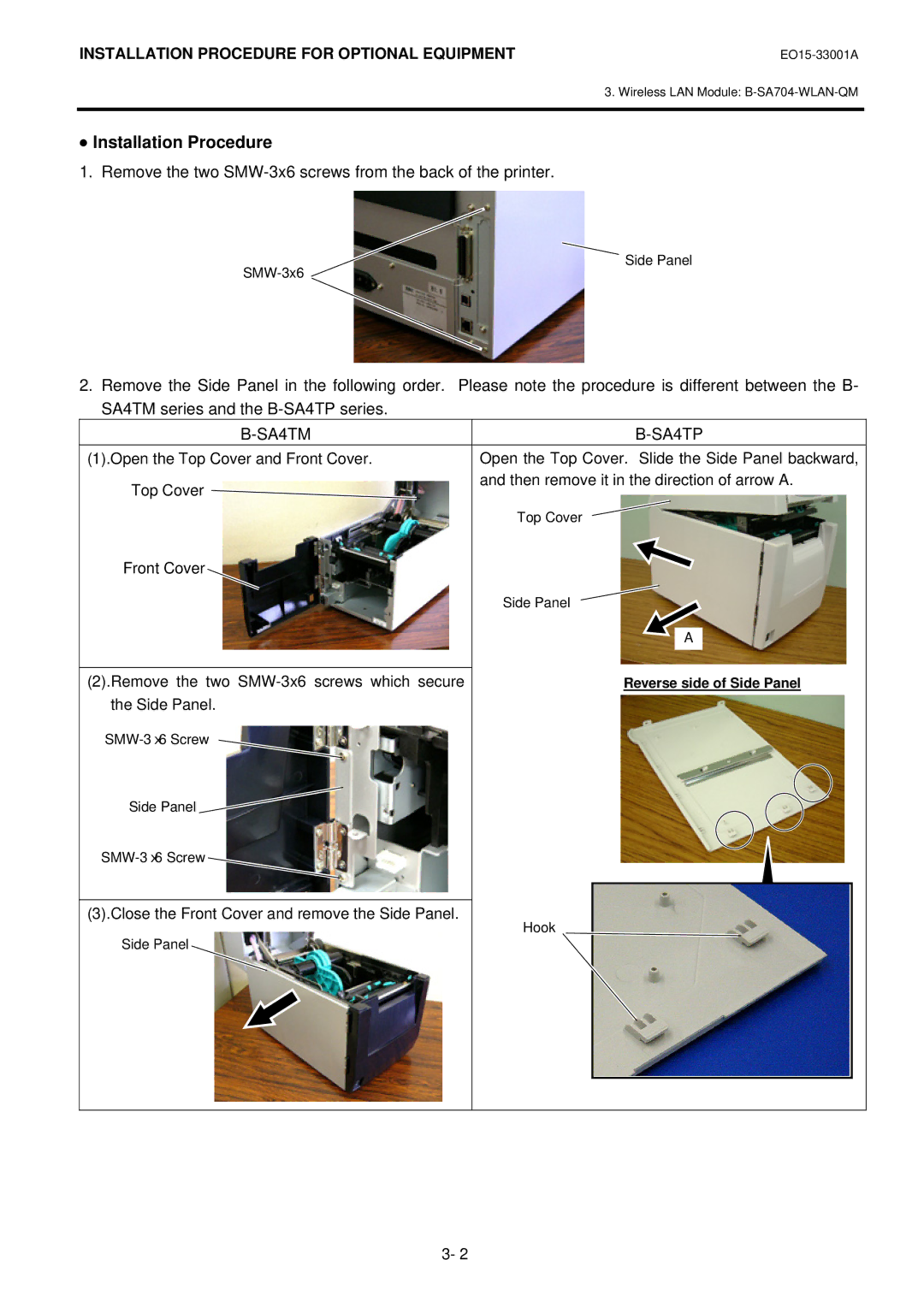
1. Remove the two SMW-3x6 screws from the back of the printer.
Side Panel
2.Remove the Side Panel in the following order. Please note the procedure is different between the B- SA4TM series and the
|
|
(1).Open the Top Cover and Front Cover. | Open the Top Cover. Slide the Side Panel backward, |
Top Cover | and then remove it in the direction of arrow A. |
| |
| Top Cover |
Front Cover |
|
| Side Panel |
| A |
|
|
(2).Remove the two | Reverse side of Side Panel |
the Side Panel. |
|
|
Side Panel![]()
![]()
(3).Close the Front Cover and remove the Side Panel.
Hook
Side Panel
3- 2