INSTALLATION PROCEDURE FOR OPTIONAL EQUIPMENT
1. Cutter Module
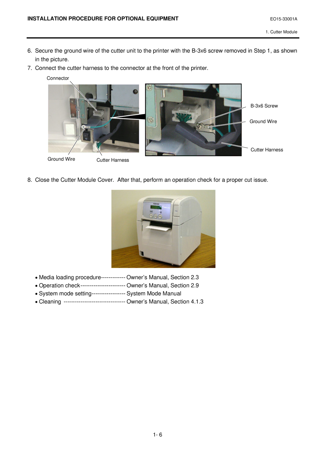
6.Secure the ground wire of the cutter unit to the printer with the
7.Connect the cutter harness to the connector at the front of the printer.
Connector
B-3x6 Screw
Ground Wire
Cutter Harness
Ground Wire | Cutter Harness |
8. Close the Cutter Module Cover. After that, perform an operation check for a proper cut issue.
• Media loading | Owner’s Manual, Section 2.3 |
• Operation | Owner’s Manual, Section 2.9 |
• System mode | System Mode Manual |
• Cleaning | Owner’s Manual, Section 4.1.3 |
1- 6