INSTALLATION PROCEDURE FOR OPTIONAL EQUIPMENT
(Revision Date: Feb. 25, 2008)
8. RFID Module:
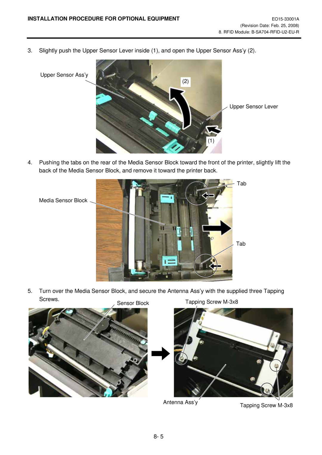
3.Slightly push the Upper Sensor Lever inside (1), and open the Upper Sensor Ass’y (2).
Upper Sensor Ass’y
(2)
Upper Sensor Lever
(1)
4.Pushing the tabs on the rear of the Media Sensor Block toward the front of the printer, slightly lift the back of the Media Sensor Block, and remove it toward the printer back.
Tab
Media Sensor Block
Tab
5.Turn over the Media Sensor Block, and secure the Antenna Ass’y with the supplied three Tapping
Screws. | Sensor Block | Tapping Screw |
|
Antenna Ass’y | Tapping Screw |
|
8- 5