INSTALLATION PROCEDURE FOR OPTIONAL EQUIPMENT
4. Serial Interface Board:
4. Attach the enclosed PCB Support Plate to the printer back with one of the enclosed
PCB Support Plate
5. Fit the Locking Support into the MAIN PC Board.
Locking Support
MAIN PC Board
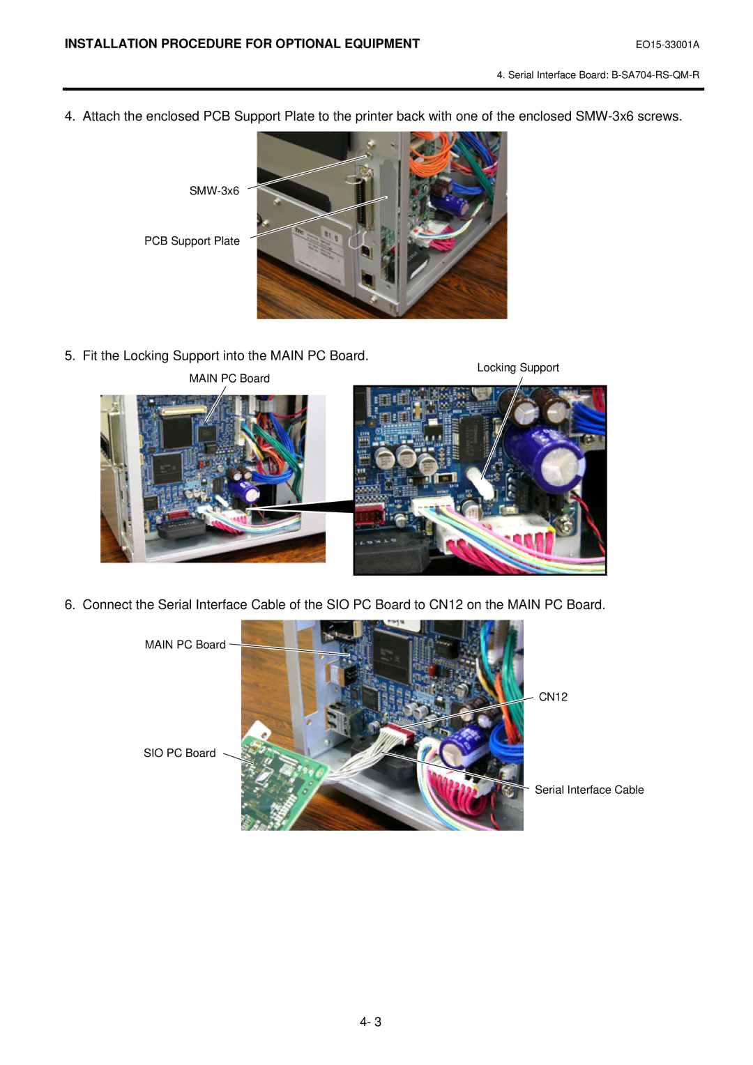
6. Connect the Serial Interface Cable of the SIO PC Board to CN12 on the MAIN PC Board.
MAIN PC Board ![]()
CN12
SIO PC Board
Serial Interface Cable
4- 3