Service of Machines
Main Service Parts for Safety
Disposition of Consumable Parts/Packing Materials
Vorsicht
Entsorgung des gebrauchten RAM-ICs inklusive
Der Lithium-Batterie nach Angaben des Herstellers
Adjustment Items Preventive Maintenance PM
Contents
Troubleshooting Based on Error Code
Firmware Updating
Appendix
Error Code List
Restart time out error
Scanner related service call
Original jam in the ADF
Original not reaching the aligning sensor
Original not reaching the exit sensor
C3F
ADF related service call
Error of aligning sensor automatic adjustment
Eeprom initializing error
Error of paper exit sensor automatic adjustment
Automatic adjustment error of bin inside paper sensor
Transport motor rotation abnormal
Bin shift motor rotation abnormal
Guide bar swing motor rotation abnormal
F11
99 08 26 17 57 236210000000 Error code
Unused
Self Diagnostic Mode
Transition diagram of self-diagnostic mode conditions
Input check Test mode
ADU side switch
A3/LD
Full COLORkey OFF, Auto COLORkey OFF, Energy SAVERkey on
Full COLORkey OFF, Auto COLORkey ON, Energy SAVERkey OFF
Full COLORkey OFF, Auto COLORkey ON, Energy SAVERkey on
Operation procedure
Full COLORkey ON, Auto COLORkey OFF, Energy SAVERkey OFF
Output check Test mode
ON/OFF
Carriage fan motor rotation when standby low speed ON/OFF
Carriage fan motor rotation when running high speed ON/OFF
Document motor indicator 1 reciprocating
SCM fan motor rotation speed Low/High
Operation procedure Group
Test print mode
Pixel modulation pattern for creating γ table
Pixel modulation pattern 1 for selecting pulse width
Pixel modulation pattern 2 for selecting pulse width
Adjustment mode
Group
OHP mode
318
Full color
~255
Fine adjustment of fuser motor rotation speed
Fine adjustment of drum motor rotation speed
Fine adjustment of feed motor rotation speed
390
Thick paper 2 mode
Thick paper 3 mode
Color registration sensor error Or 16 or above Normal
Right margin
Write start position adjust 2nd cassette
Default 9 68 msec
Modulation mode switching, type a
Modulation mode switching, type B
Density adjustment density curve selection
Color mode black text γ curve set selection
Monochrome mode black text γ curve set
Monitor patch output ON/OFF switching
Fine adjustment Text
Center setting Printed image
Darker setting Printed image
Manual density Full color Text/Photo
Lighter setting Printed image
Sity fine adjust Text
Made at the light side become
Lighter
Total hue adjustment
For ID Full color non-text area Y
For ID Full color non-text area M
For ID Full color non-text area C
Total luminance adjustment
Total saturation adjustment
Tend to be judged as color Auto-color mode
Adjustment
AI mode setting Time-out setting
Macro recognition Pre-process text threshold Adjustment
Macro recognition Pre-process shading Threshold adjustment
Adjustment Map
Micro recognition Text emphasis adjustment
When the value increases, the im
Default is equivalent to
Micro recognition Logo text inside threshold
Fixed black ratio adjustment, type a
Fixed black ratio adjustment, type B
Fixed black ratio adjustment, type C
Fixed black ratio adjustment, type D
Color mode, black text γ adjustment
Monochrome mode, black text γ adjustment
~255 Mode become denser
Color balance
Color balance Text/Photo Low density
High density
Text Low density
Photo Low density
Output value indica When the light source
Procedure Group
Power Cancel Clear
Energy Saver Start
Setting mode
Following items can be set or changed in this mode
Timer for Print job start up time Set number Seconds
Is disabled
All clearing by key copy counter Disabled 1Enabled Removal
Original
269
Radf
Image quality control auto-start
When 1 is set, a paper source becomes
Disabled Enabled
Start count setting of developer
Paper source priority A4/LT
Secondary scanning 100% 1 101% Reproduction ratio adjustment
Radf priority mode Continuous feeding by Start key
Function clearing immediately Invalid 1 Valid After copying
Image repeat gap
Invalid Other than
Power shutoff Low power
All clearing of image processing Adjustment values
All clearing of pulse width Selection adjustment results
All clearing of γ correction Table adjustment results
Refer to Counter function and maintenance chacke list
Full-color print counter Copier
Display of counter value Code 08-802 is Reflected
Black print counter Copier
Radf original counter
Drum C life counter display/0
Refer to Counter function and maintenance check list
906
Does not start 1 Starts
Available during MFP
Invalid Valid
System mode display
Procedure for registering ID codes
Registering/changing ID codes
Correcting ID code
Adjustment Order Copy Image Related Adjustment
Automatic Adjustment of the Auto-Toner Circuit
100% AA3
Wait
Remove the developer cartridges Install the toner cartridges
Replace disabled parts
03-113 ON, 03-163 OFF
Check if the developer cartridge gears rotate properly
Replace EPU
Automatic Initialization of Image Quality Control
Copy Image Dimensional Adjustment
XXX
Which occurs when the paper scrapes on
Long size 439 441 443 445 Short size 440 442 444 446
447 448
449
Feed motor speed adjustment
Printer related adjustment
FC-22 Adjustment
Grid pattern
Scanner related adjustment
Step
Application Method of the Adhesive for Screw Locking
Application area Carriage frame Mirror
Image skewing adjustment
FC-22 Adjustment
LCF
FC-22 Adjustment
Chart TCC-1
Adjustment order
Toshiba Color Chart
Place the Patch chart for gamma adjustment produced in step
Shown. Press Start to have the adjustment results reflected
Transfer belt
Input 2 with digital keys, and press Start and then Inter
FC-22 Adjustment
Remarks
550 551
Manual-density
Full Dark step value Dark side becomes 570 571
Copy mode Item to be
Photo Map Remarks Adjusted
Acceptable values 0 to
255
Copy mode Item to be adjusted Remarks
Color 698 699
702 Offset value for
Background Background becomes
Judgment Threshold for ACS
AI Mode Setting
Code Color mode Copy mode Content
AI photo area Have to make adjustment by compromising
AI text area Image becomes
AI photo area Smaller the value, the less moire tends to
Settings after replacing main high-voltage transformers
High-Voltage Transformer Settings
Overview
Settings after replacing transfer transformer
Adjusting Doctor-to-Sleeve Gap
Adjusting the Scanner Section
Adjusting the Carriages
Installing the carriage drive wires to the wire pulleys
Relationship between wound turns and wire holder jigs
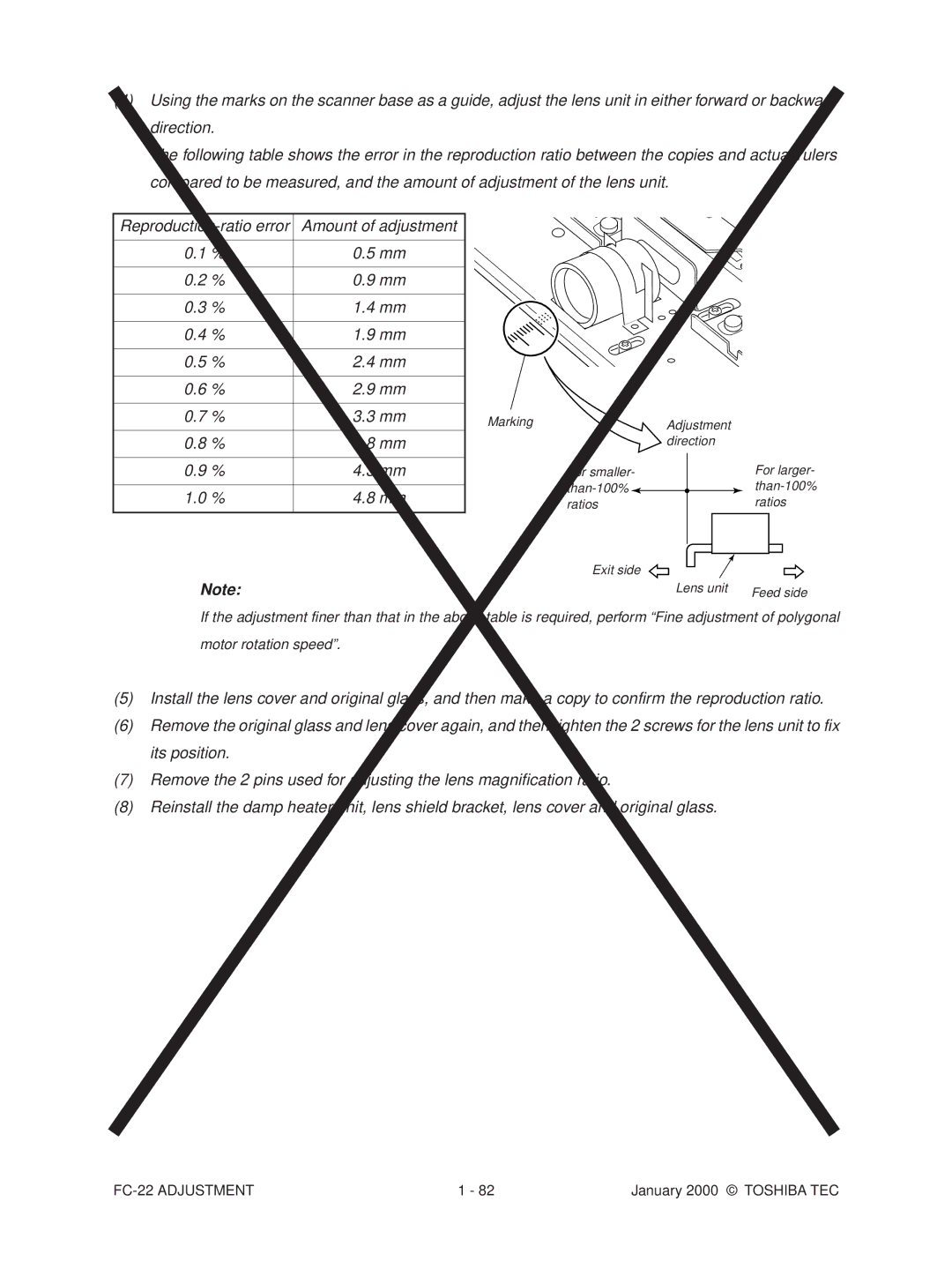
Lens Unit
Loosen 2 screws for fixing the lens unit
Marking Adjustment Direction
FC-22 Adjustment
Adjusting the Cassette for Sidewise Deviation
Key Copy Counter MU-8, MU-10
08 setting mode, enter 3 under code
Preventive Maintenance PM
Types of Preventive Maintenance
Symbols used in the checklist For FC-22
Preventive Maintenance Checklist
Symbols used in the checklist For FC-15
General Maintenance Checklist FC-22
Original glass Z60or a Platen cover Mirror
TBU
Color Maintenance Checklist FC-22
General Maintenance Checklist FC-15
Image quality sensor’s area Z40
Color Maintenance Checklist FC-15
53 52 51 54 56 57
Front sectional view
Processing unit EPU
Front-side drive system
Such as screws on the table
Developer material
FC-22 Preventive Maintenance
PM Kit
SR-FC22H
20K kit
Page
Test chart No. TCC-1
List of Adjustment Tools
Scanner carriage jig
Precautions for Storing Toshiba Supplies
Checking and Cleaning of the Photoconductive Drum
FC-22 Supplies
Checking and Cleaning of the Fuser Rollers
Checking and Replacing the Transfer Belt
Checking and Replacing the Transfer Roller
Troubleshooting Based on Error Code
Reconnect the connector. Replace the harness
Is the fuser motor rotating?
Disconnected?
E03 Paper remaining inside the copier at power on
Paper feeding jam E11 Paper misfeed from the ADU
E12 Paper misfeed from the bypass
Replace the cassette-feed jam sensor Replace the LGC board
E19 Paper misfeed from the LCF
Reconnect the connector. Replace the harness
Cover open jam E41 Front cover opened during copying
Close the front cover or the paper exit unit
E42 Side door opened during copying
Is the side door open?
E45 LCF jam access cover opened during copying
Is the LCF jam access cover open?
Close the LCF jam access cover
E43 ADU unit pulled out during copying
Is the bypass unit open?
E46 Bypass unit opened during copying
Close the bypass unit
E52 Paper not reaching the ADU path sensor
Have too many originals been placed?
Original does not reach the aligning roller
Original stops, skewed on the original glass
Paper jam in the sorter EA1 Paper transport delay jam
Paper transport stop jam
EA4 Sorter front door opened during copying
Paper remaining on the sorter transport path at power on
Is the stapler unit cover securely closed?
EA5
Staple jam
EC3 OHP sheet used in non-OHP mode
Is the ADU motor rotating properly?
C09 Black developer motor rotation abnormal
Is the black developer motor rotating properly?
C0A Color developer motor rotation abnormal
Is the color developer motor rotating properly?
Drum motor K rotation abnormal
Drum motor C rotation abnormal
Drum motor M rotation abnormal
Drum motor Y rotation abnormal
Put the belt on properly
C12 ADU paper end guide function abnormal
Replace the gear
Do the switches and sensors in the LCF unit function?
C18 LCF tray function abnormal
C28
C29 Exposure lamp disconnection detected
Replace the harness. Reconnect the connectors
Is used toner jammed? Is any abnormal mechanical load found?
C33 Developer removal shutter function abnormal
C35 Transfer belt unit contact/release function abnormal
C37 Transfer belt motor rotation abnormal
C38 C39
Replace the auto toner sensor Replace the LGC board
Reinstall the main charger
Reconnect the wire cleaner home position switch
Reconnect the wire cleaner limit switch
Securely
C42 Thermistor abnormal after the copier becomes ready
FC-22 Troubleshooting
Error C7
C48 Heater abnormal high temperature
C41
FC-22 Troubleshooting
FC-22 Troubleshooting
FC-22 Troubleshooting
C73 Eeprom initializing error
C74 Error of exit sensor automatic adjustment
Other service calls C94 Main-CPU abnormal
Observe the condition for a while
C9A Main memory abnormal
C9E IMC board connection abnormal
Replace the laser optical unit
CA2 H-SYNC abnormal
Is the polygonal motor rotating?
Sorter related service call
Transport motor rotation abnormal
CC3
Bin-shift motor rotation abnormal
Guide bar swing motor rotation abnormal
Stapler-unit swing motor rotation abnormal
Automatic adjustment error of bin inside paper sensor
CCA
No power being supplied
Press the circuit breaker
Is the fuse blown out?
Replace the fuse
Image quality related service call
Image quality sensor abnormal OFF level
CE2
Image quality sensor no pattern level
CE4 Image quality control test pattern abnormal
CE5 Temperature/humidity sensor upper-limit abnormal
CF1 Color registration control abnormal
FC-22 Troubleshooting
FC-22 Troubleshooting
FC-22 Troubleshooting
F11 Communications error between System-CPU and Scanner-CPU
FC-22 Troubleshooting
Troubleshooting of Image
Color deviation Symptoms
Few steps at a time
Uneven pitch and blur Symptoms
FC-22 Troubleshooting
FC-22 Troubleshooting
Defect of image density, color reproduction and gray balance
Background Fogging
Moire/lack of sharpness
Lack of sharpness
Toner offset Feeding direction
Vents because they have bad effect on drum
Fuser roller pressure defect
Check/correct developer sleeve coupling engaging
Solid copy Feeding direction
White banding in feeding direction directionFeeding
Check/correct related circuits
Skew slantwise copying Feeding direction
LCF
Color banding in feeding direction Feeding direction
FC-22 Troubleshooting
White spots Feeding direaction
Cause/Defect area Step Check items Measures Developer unit
Poor image transfer Feeding direction
Uneven image density Feeding direction
Cause/Defect area
Image dislocation in feeding direction Feeding direction
Image jittering Feeding direction
Poor cleaning Feeding direction
Oil roller Life ended? Fuser roller
Uneven light distribution Feeding direction
Blotched image Feeding direction
Outline
3 9 Mode Operation
Preparation of PC
\WEBSHARE\FTPROOT
FC-22 Firmware Updating
Firmware update operation
One of the followings SJP, SEU, SUC, SX
SJP
Case of 1
Case of #1 #3
Error Message
Case of #1 #3 Following screen is displayed after finished
Further procedure is the same as normal sequence
Following screen will be displayed in 3 9 mode
Screen details
Press Start Key
Case of #1- #3
’ Press Start Key
Error Occurrence Area Power OFF
Installation Instructions for Firmware Update through PC
System configuration
Preparation of PC to use a network
FC-22 Firmware Updating
FC-22 Firmware Updating
FC-22 Firmware Updating
FC-22 Firmware Updating
FC-22 Firmware Updating
FC-22 Firmware Updating
FC-22 Firmware Updating
FC-22 Firmware Updating
FC-22 Firmware Updating
Installation of FTP server
FC-22 Firmware Updating
FC-22 Firmware Updating
FC-22 Firmware Updating
FC-22 Firmware Updating
Wire Harness Connection Diagrams
AC Wire Harness
DC Wire Harness
January 20000 Toshiba TEC