AIR-CONDITIONER
Contents
New Refrigerant Air Conditioner Installation
For general public use
For Reference
Table of models that can be connected
Table of models that can be used in combination
Specifications Heat pump models
Specifications Cooling-only models
Heating RAS-M14EAV-E
Performance specifications combinations of indoor unit
Cooling RAS-M14EAV-E, RAS-M14EACV-E
Cooling RAS-M18EAV-E , RAS-M18EACV-E
HeatingRAS-M18EAV-E
Heating RAS-M14EAV-E
Operation Characteristic Curve
Capacity Variation Ratio According to Temperature
105 Units operating 100 Ratio
Heating RAS-M18EAV-E
Cooling
Piping Materials and Joints Used
Safety During Installation/Servicing
Refrigerant Piping Installation
Outer diameter mm R410A R22
Processing of Piping Materials
1 Thicknesses of annealed copper pipes Thickness mm
Nominal diameter
Width
Flare tool for R410A Conventional flare tool
Clutch type Wing nut type
Diameter
Nm kgfcm
Diameter Wrenches available on the market
General tools Conventional tools can be used
Tools
Required Tools
1 Configuration of refrigerant charging
Recharging of Refrigerant
Flux
Brazing of Pipes
Materials for Brazing
Cylinder with siphon Cylinder without siphon
Brazing
Never use gas other than Nitrogen gas
Indoor Unit
Outdoor Unit
Color Identification
Outdoor Unit
Parts name
RAS-M14EAV-E, RAS-M14EACV-E, RAS-M18EAV-E, RAS-M18EACV-E
Refrigerant Cycle Diagram
RAS-M13EKCVP-E, RAS-M10EKCVP-E RAS- M14EACV-E
RAS-B16EKVP-E, RAS-B13EKVP-E, RAS-B10KVP-E RAS-M18EAV-E
21 to 30m
Operation Data
Cooling RAS-M14EAV-E, RAS-M14EACV-E
Remote Controller
RAS-M10EKCVP-E, RAS-M13EKCVP-E, RAS-M16EKCVP-E
Control Blok Diagram Outdoor unit
MCC-5015 SUB P.C.B MCC-5009 SUB P.C.B
Outline of Air Conditioner Control
Operation Description Contents
Operation flow and applicable data, etc Description
Ing of cooling dry and heating, fan
When combined operation consist
Cleaning operation and heating is
Air purification and heating, or
Operation flow and applicable data, etc Description
Indoor fan air flow rate
Symbols
Cooling operation
Cold draft preventive control
Heating operation Heat pump model
Basic fan control
Starting and in stability
Mode, by the conditions
Outdoor temperatureTo
According to each operation
Compressor revolution,
MIN MAX
Each operating mode is shown
Controller setting temperature
Ts and the indoor temperature
Capacity Indoor unit a and Indoor unit B
Operation flow and applicable data, etc
Cooling/dry operation
Finish of defrost operation
Condition
Defrost operation
Returning from defrost operation
Louver position in heating operation
Auto COOL/Dry
Cooling operation
Heating operation
Operation flow and applicable data, etc Description
Operation of air conditioner + air purifier
When the previous operation was
Fan speed is Fan Auto mode varies
An operation of air conditioner + air
Purpose
Purpose
Operation
Operation
PMV
Clean operation times
Clean operation
Setting the clean operation
Outline diagram of P.C. board
Setting the remote controller
Setting the selector switch on the main unit
How to Set the Auto Restart Function
Auto Restart Function
Power Failure During Timer Operation
Filter Indicator
How to Cancel the Auto Restart Function
How to Turn Off Filter Indicator
Remote Controller and Its Fuctions
Parts Name of Remote Controller
Name and Functions of Indications on Remote Controller
Display
Page
Installation Diagram of Indoor and Outdoor Units
Others
Accessory and Installation Parts
Attachment bolt arrangement of outdoor unit
Option
New tools for R410A
Installation/Service Tools
Changes in the product and components
Remote control
Installation of Indoor Unit Installation Location
Drilling a Hole and Mounting Installation Plate
When installing the refrigerant pipes from the rear
Electrical Work
Mounting the installation plate
When the installation plate is directly mounted on the wall
Wiring Connection
How to connect the connecting cable
Piping and Drain Hose Installation
Piping and drain hose forming
Left-hand connection with piping
Case of right or left piping
Case of bottom right or bottom left piping
12.7 mm
Indoor Unit Installation
Drainage
Table of models that can be used in combination
Precautions for Adding Refrigerant
Installation of Outdoor Unit
Installation diagram of outdoor units
You will need to add 20 g of refrigerant per meter
Draining the water
Flaring
Tighten the connection
Use a vacuum pump
Connectable capacity class Total
Model
Packed valve handling precautions
Stripping length of connecting cable
Check and Test Operation
Miswiring Mis-piping Check
Grounding
This air conditioner must be grounded without fail
Test Operation Gas Leak Test
Auto Restart Setting
Remote Control Selector Switch Setting
Test Operation
D12 D13 Normal running
Self-Diagnosis by LED Indication
D09 D10
Troubleshooting Procedure
Precautions when handling the new inverter 3DV Inverter
Do not lay the circuit board assembly flat
Control circuitry has an uninsulated construction
Inverter cover
Board
First Confirmation
Confirmation of Power Supply
Confirmation of Power Voltage
Operation Which is not a Trouble Program Operation
Which lamp does flash?
Primary Judgment
Judgment by Flashing LED of Indoor Unit
Block display Description for self-diagnosis Code
Push START/STOP button to release the service mode
Self-Diagnosis by Remote Controller Check Code
How to Use Remote Controller in Service Mode
Push on or OFF button
Block distinction
Block distinction Operation of diagnosis function
Power is not turned on Does not operate entirely
Judgment of Trouble by Every Symptom
Indoor Unit Including Remote Controller
Power is not turned on though Indoor P.C. board is replaced
Only the indoor motor fan does not operate
Is it possible to
Cause
Start to operate by Automatic restart
Troubleshooting for remote controller
With tip of pencil
Terminal block at indoor side
Wiring Failure Interconnecting and Serial Signal Wire
Outdoor unit does not operate
To item of Outdoor unit does not operate
Check Code 1C Miswiring in indoor/outdoor units and 1E
Check procedure
Trouble Diagnosis by Outdoor LED
Primary check
Troubleshooting
How to Check Whether the Air Purifier is Good or Not
Operation check
How to Check Whether the Minus Ion Generator is Good or Not
Primary check
Diagnosis/Process flowchart Contents Summary
How to Diagnose Trouble in Outdoor Unit
Summarized Inner Diagnosis of Inverter Assembly
Operating precautions
How to Check Simply the Main Parts
How to Check the P.C. Board Indoor Unit
Inspection procedures
Check procedures
Procedure Check points Causes
Sensor characteristic table
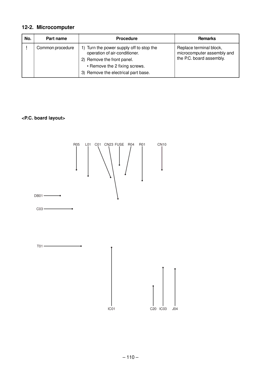
11-9-2. P.C. Board Layout
Outdoor Unit
Part name Checking procedure
Indoor Unit Other Parts
Checking Method for Each Part
Case that product is good
Cause
Symptom
100
101
Part name Procedures Remarks
12-1 Indoor Unit
How to assemble the front panel
102
103
104
No. Part name Procedures
High voltage How to assemble the high voltage generator
Remarks
How to assemble the electric parts assembly
105
106
107
Slightly, and remove the bearing base
108
109
Cross flow Caution at reassembling
110
Part name Procedure Remarks
12-2 Microcomputer
Attachment
111
Detachment
Part name Procedures
112
According to trouble type in some cases
No. Part name Procedure Remarks
113
Polarity with screwdriver, etc. for discharging
Sub P.C. board
114
Main P.C. board
Board base
Side cabinet left
115
Side cabinet right
Flange nut
116
Fan motor
Handling precaution
117
118
Figure shown on the left
Remarks
119
Part name
Parts name Qty Remarks
120
121
Exploded Views and Parts List
122
123
Location No Description
124
Cooling only model Heat pump model
13-3. P.C. Board Layout
125
Appendix-1
Required parts for installation work Recommendation
Part name ’ty Specifications/Vendor Remarks
Appendix-2
Required tools for installation work
Part name Specifications Usage
Cord heater installation wiring diagram
Appendix-3
Cord heater installation work procedure
Appendix-4
Appendix-5
Appendix-6
Appendix-7
Photo / Explanatory diagram Procedure Assembly
Appendix-8
Drawing of thermostat fixing plate
Material SGCC-Z08, Thickness 0.8t Appendix-9
Appendix-10