SPLIT TYPE
AIR-CONDITIONER
FILE NO. A04-015
CONTENTS
For general public use
1. SAFETY PRECAUTIONS
DANGER
For Reference
– 4 –
Table of models that can be used in combination
2. SPECIFICATIONS
Table of models that can be connected
– 5 –
– 6 –
Page
Cooling Indoor: DB/WB=27/19C Outdoor: DB=35C
– 8 –
Heating Indoor: DB=20C Outdoor: DB/WB=7/6C
<Cooling> RAS-M18EAV-E , RAS-M18EACV-E
– 9 –
<Heating>RAS-M18EAV-E
<Cooling> RAS-M14EAV-E, RAS-M14EACV-E
2-2-1.Operation Characteristic Curve
– 10 –
RAS-M14EAV-E, RAS-M14EACV-E <Cooling>
<Cooling> RAS-M18EAV-E, RAS-M18EACV-E
2-2-3.Operation Characteristic Curve
– 11 –
RAS-M18EAV-E, RAS-M18EACV-E
3. REFRIGERANT R410A
3-1.Safety During Installation/Servicing
3-2.Refrigerant Piping Installation
3-2-1.Piping Materials and Joints Used
3-2-2.Processing of Piping Materials
– 13 –
– 14 –
– 15 –
General tools Conventional tools can be used
3-3.Tools
3-3-1.Required Tools
– 16 –
3-4.Recharging of Refrigerant
– 17 –
3-5-2.Flux
3-5.Brazing of Pipes
3-5-1.Materials for Brazing
– 18 –
Never use gas other than Nitrogen gas
3-5-3.Brazing
– 19 –
– 20 –
4. CONSTRUCTION VIEWS
4-1.Indoor Unit
RAS-B10EKVP-E RAS-B13EKVP-E RAS-B16EKVP-E
4-2.Outdoor Unit
– 21 –
T3.15A
5. WIRING DIAGRAM
5-1.Indoor Unit
– 22 –
5-2.Outdoor Unit
– 23 –
RAS-B16EKVP-E, RAS-B13EKVP-E, RAS-B10EKVP-E
Specifications
– 24 –
RAS-M16EKCVP-E, RAS-M13EKCVP-E, RAS-M10EKCVP-E
Parts name
6-2.Outdoor Unit
– 25 –
Model name
– 26 –
7. REFRIGERANT CYCLE DIAGRAM
7-1.Refrigerant Cycle Diagram
RAS-B13EKVP-E, RAS-B10EKVP-E RAS-M14EAV-E
RAS-M13EKCVP-E, RAS-M10EKCVP-ERAS- M14EACV-E
Page
– 29 –
7-2.Operation Data
– 30 –
8-1.Indoor Unit
8. CONTROL BLOCK DIAGRAM
REMOTE CONTROLLER
– 31 –
REMOTE CONTROLLER
RAS-M10EKCVP-E, RAS-M13EKCVP-E, RAS-M16EKCVP-E
M.C.U
CONTROL BLOK DIAGRAM Outdoor unit
– 33 –
M.C.U
9-1.Outline of Air Conditioner Control
9. OPERATION DESCRIPTION
– 34 –
9-2.Operation Description
Contents
Page
Page
– 37 –
Ts –
– 38 –
Ts +
Fan only operation Cooling-onlymodel
Item
Symbols
– 39 –
Operation flow and applicable data, etc
Description
– 40 –
Operation flow and applicable data, etc
<In heating operation> Heat pump model
Item
outdoor temperatureTo and
– 41 –
Operation flow and applicable data, etc
– 42 –
– 43 –
Operation flow and applicable data, etc
– 44 –
Item
<In cooling/dry operation>
Operation flow and applicable data, etc
– 45 –
Item
Description
Operation flow and applicable data, etc
– 46 –
Item
Description
Operation flow and applicable data, etc
– 47 –
Item
Description
Operation flow and applicable data, etc
– 48 –
Description
– 49 –
3. Operation
1. Purpose
2. Description
1. Purpose
Operation flow and applicable data, etc
– 51 –
Description
Item
Clean operation
– 52 –
Operation flow and applicable data, etc
– 53 –
Setting the clean operation
Outline diagram of P.C. board
Item
– 54 –
Setting the remote controller
Setting the selector switch on the main unit
Item
9-3.Auto Restart Function
9-3-1.How to Set the Auto Restart Function
– 55 –
9-3-3.Power Failure During Timer Operation
9-4.FILTER Indicator
9-3-2.How to Cancel the Auto Restart Function
9-4-1.How to Turn Off FILTER Indicator
9-5-1.Parts Name of Remote Controller
9-5.Remote Controller and Its Fuctions
– 57 –
Display
– 58 –
adbhj
Hi-POWERbutton on the remote controller is pushed
9-6. Hi-POWERMode
– 59 –
10. INSTALLATION PROCEDURE
10-2.OptionalParts, Accesories and Tools
Optional Installation Parts
Accessory and Installation Parts
– 61 –
Installation/Service Tools
– 62 –
Drilling a Hole and Mounting Installation Plate
10-3.Installation of Indoor Unit
Installation Location
– 63 –
Electrical Work
– 64 –
Wiring Connection
– 65 –
Piping and Drain Hose Installation
– 66 –
In case of bottom right or bottom left piping
– 67 –
In case of right or left piping
Left-handconnection with piping
Drainage
Indoor Unit Installation
– 68 –
NOTES
Table of models that can be used in combination
– 69 –
10-5-1.Installation Location
10-5.Installation of Outdoor Unit
– 70 –
Draining the water
– 71 –
10-5-2.Refrigerant Piping Connection
– 72 –
10-5-3.Evacuating
– 73 –
10-5-4.Wiring Connection
– 74 –
10-7.Check and Test Operation
Miswiring Mis-pipingCheck
10-6.Grounding
– 75 –
10-8.TestOperation Gas Leak Test
Auto Restart Setting
Remote Control Selector Switch Setting
Test Operation
Self-Diagnosisby LED Indication
10-9.USEFUL FUNCTIONS
– 77 –
11. HOW TO DIAGNOSE THE TROUBLE
– 78 –
– 79 –
< Discharging method >
11-1.First Confirmation
11-1-1.Confirmation of Power Supply
11-1-2.Confirmation of Power Voltage
– 80 –
– 81 –
11-2.Primary Judgment
11-3.Judgment by Flashing LED of Indoor Unit
NOTES
– 82 –
11-4-2.Caution at Servicing
– 83 –
Operation of diagnosis function
– 84 –
Block distinction
Judgment and action
<Confirmation procedure>
11-5.Judgment of Trouble by Every Symptom
11-5-1.Indoor Unit Including Remote Controller
– 85 –
Primary check
– 86 –
3 Only the indoor motor fan does not operate
<Inspection procedure>
<Cause>
– 88 –
5 Troubleshooting for remote controller
<Primary check>
– 89 –
1Outdoor unit does not operate
<Check procedure>
– 90 –
11-7.Trouble Diagnosis by Outdoor LED
– 91 –
– 92 –
11-7.Troubleshooting
How to check output of the air purifier
<Caution on High Voltage!!>
Primary check
– 93 –
Operation check
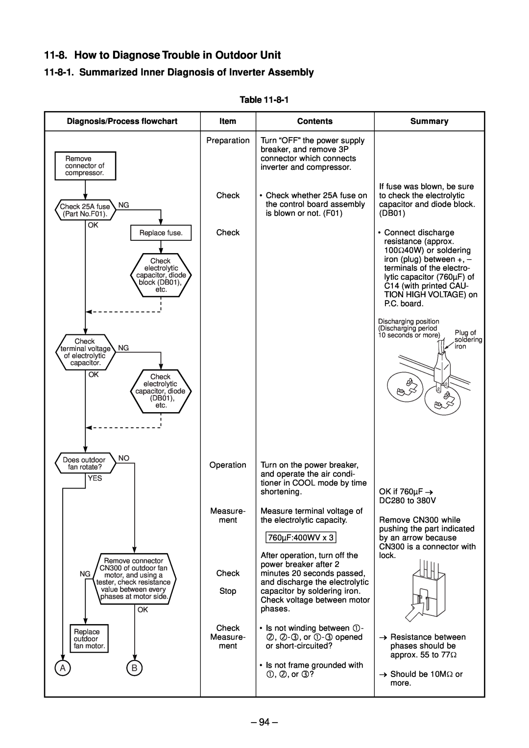
– 94 –
Diagnosis/Process flowchart
Contents
Item
11-9-1.How to Check the P.C. Board Indoor Unit
11-9.How to Check Simply the Main Parts
– 95 –
– 96 –
3 Check procedures Table
Procedure
Check points
11-9-2.P.C. Board Layout
1 Sensor characteristic table
– 97 –
11-9-4.Outdoor Unit
11-9-3.Indoor Unit Other Parts
– 98 –
11-9-5.Checking Method for Each Part
+ ~ ~
– 99 –
– 100 –
1.Symptom
2. Cause
Indoor Unit
12. HOW TO REPLACE THE MAIN PARTS
12-1
– 101 –
<How to assemble the front panel>
Procedures
installation plate
102
– 103 –
– 104 –
Procedures
No. Part name
– 105 –
– 106 –
107
108
No. Part name
Procedures
– 109 –
Cross flow <Caution at reassembling>
– 110 –
12-2
Microcomputer
P.C. board layout
12-3.Outdoor Unit
– 111 –
Part name
Procedures
112
Detachment
113
– 114 –
Part name
Procedures
– 115 –
Remarks
– 116 –
– 117 –
Part name
Procedures
– 118 –
Remarks
– 119 –
Remarks
– 120 –
Outdoor unit main PCB MCC-5009
– 121 –
Outdoor unit Sub PCB MCC-5009
13-1.Indoor Unit
13. EXPLODED VIEWS AND PARTS LIST
– 122 –
– 123 –
13-2.Outdoor Unit
– 124 –
13-3.P.C. Board Layout
125
Appendix
Cord Heater Installation Work
Specifications/Vendor
Appendix-1
Appendix
Specifications/Vendor
Specifications
Appendix-2
Appendix
3. Cord heater installation wiring diagram
Appendix-3
Procedure
4. Cord heater installation work procedure
Photo / Explanatory diagram
Appendix
Appendix
Photo / Explanatory diagram
Procedure
Appendix-5
Appendix
Photo / Explanatory diagram
Procedure
Appendix-6
Appendix
Photo / Explanatory diagram
Procedure
Appendix-7
Assembly
Photo / Explanatory diagram
Procedure
Appendix
8 5.8
Appendix
5. Drawing of thermostat fixing plate
11 28 11 18
Appendix
Appendix-10