STE 58760
Repeat this key operation until the "JLIMIT>" command appears on the LCD display.
NEXT
F6
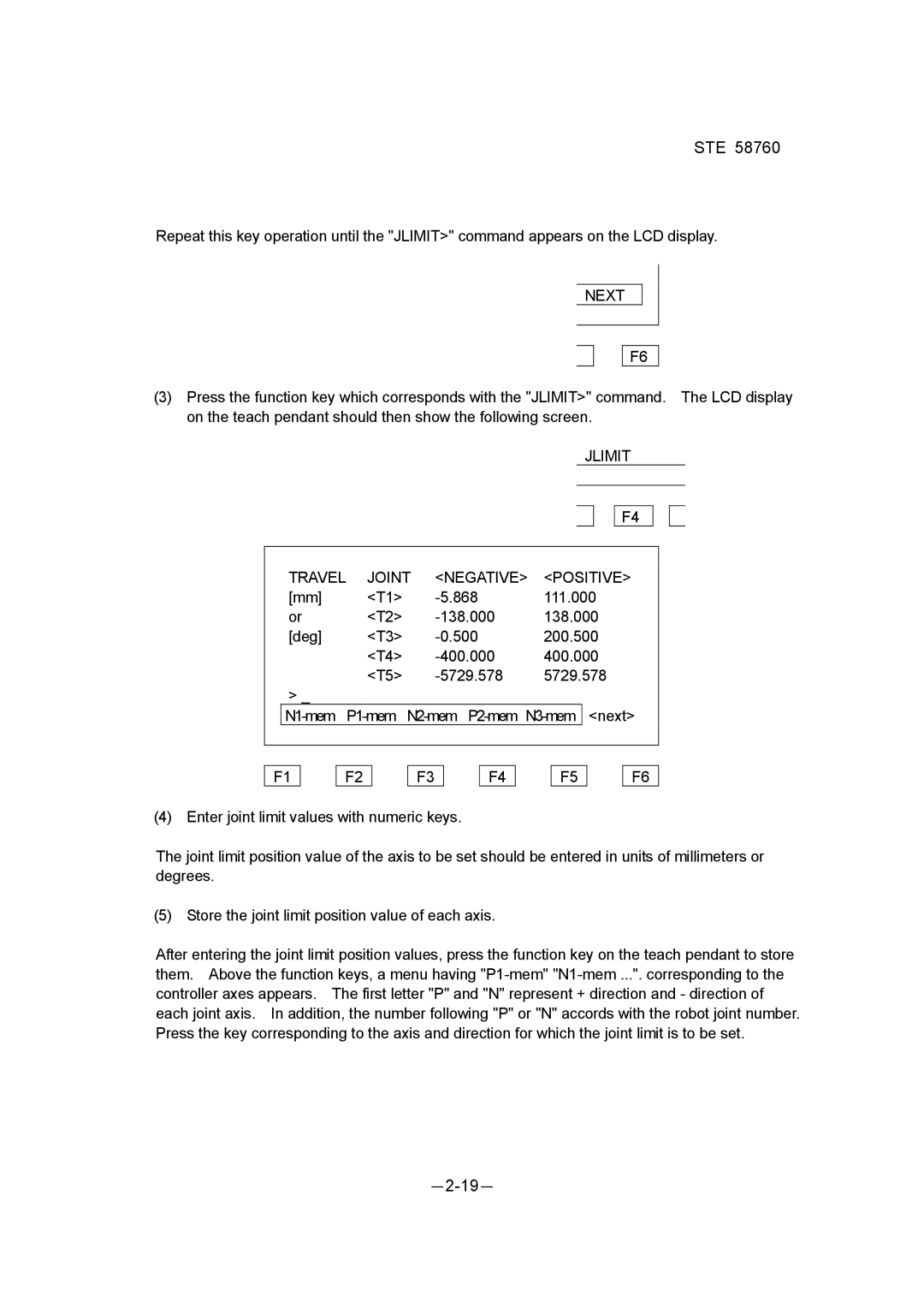
(3)Press the function key which corresponds with the "JLIMIT>" command. The LCD display on the teach pendant should then show the following screen.
|
|
|
| JLIMIT |
| ||
|
|
|
|
|
|
|
|
|
|
|
|
|
| F4 |
|
|
|
|
|
| |||
TRAVEL | JOINT | <NEGATIVE> | <POSITIVE> |
| |||
[mm] | <T1> | 111.000 |
|
| |||
or | <T2> | 138.000 |
|
| |||
[deg] | <T3> | 200.500 |
|
| |||
| <T4> | 400.000 |
|
| |||
| <T5> | 5729.578 |
|
| |||
> _
F1
F2
F3
F4
F5
F6
(4) Enter joint limit values with numeric keys.
The joint limit position value of the axis to be set should be entered in units of millimeters or degrees.
(5) Store the joint limit position value of each axis.
After entering the joint limit position values, press the function key on the teach pendant to store them. Above the function keys, a menu having