Chapter 1: ML605 Evaluation Board
User LEDs
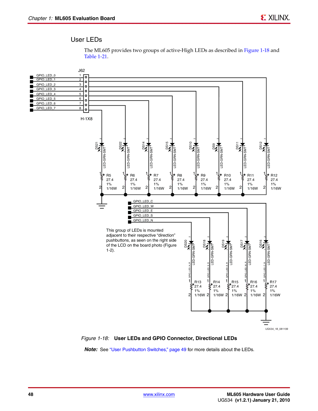
The ML605 provides two groups of
GPIO_LED_0 GPIO_LED_1
GPIO_LED_2 GPIO_LED_3
GPIO_LED_4
GPIO_LED_5
GPIO_LED_6
GPIO_LED_7
J62
1
2
3
4
5
6 |
|
|
|
|
|
|
|
|
|
|
|
|
|
|
|
|
|
|
|
|
|
7 |
|
|
|
|
|
|
|
|
|
|
|
|
|
|
|
|
|
|
|
|
|
8 |
|
|
|
|
|
|
|
|
|
|
|
|
|
|
|
|
|
|
|
|
|
|
|
|
|
|
|
|
|
|
|
|
|
|
|
|
|
|
|
|
|
|
|
| 2 |
| 2 |
| 2 |
| 2 |
| 2 |
|
|
| 2 |
|
| 2 |
|
|
| 2 |
|
DS21 | 1 | DS22 1 | DS14 | 1 | DS15 | 1 | DS10 | 1 |
| DS9 | 1 | DS11 | 1 |
| DS12 | 1 | |||||
| 1 | R5 | 1 | R6 | 1 | R7 | 1 | R8 | 1 | R9 |
|
| 1 | R10 | 1 |
| R11 |
| 1 | R12 | |
|
|
|
|
|
|
|
|
|
|
|
|
| |||||||||
|
| 27.4 |
| 27.4 |
| 27.4 |
| 27.4 |
| 27.4 |
|
| 27.4 |
|
| 27.4 |
|
| 27.4 | ||
| 2 | 1% | 2 | 1% | 2 | 1% | 2 | 1% | 2 | 1% |
|
| 2 | 1% |
| 2 |
| 1% |
| 2 | 1% |
| 1/16W | 1/16W | 1/16W | 1/16W | 1/16W | 1/16W |
| 1/16W |
| 1/16W | |||||||||||
|
|
|
| GPIO_LED_C |
|
|
|
|
|
|
|
|
|
|
|
|
|
|
|
| |
|
|
|
| GPIO_LED_W |
|
|
|
|
|
|
|
|
|
|
|
|
|
|
|
| |
|
|
|
| GPIO_LED_E |
|
|
|
|
|
|
|
|
|
|
|
|
|
|
|
| |
|
|
|
| GPIO_LED_S |
|
|
|
|
|
|
|
|
|
|
|
|
|
|
|
| |
|
|
|
| GPIO_LED_N |
|
|
|
|
|
|
|
|
|
|
|
|
|
|
|
| |
|
| This group of LEDs is mounted |
|
|
|
|
|
|
|
|
|
|
|
|
|
|
| ||||
|
| adjacent to their respective “direction” | 2 |
|
| 2 |
|
| 2 |
|
| 2 |
|
| 2 |
| |||||
|
| pushbuttons, as seen on the right side | DS20 |
| DS18 |
|
|
| DS19 |
| DS17 |
|
| DS16 |
|
| |||||
|
| of the LCD on the board photo (Figure | MT |
| MT |
| MT |
| MT |
| MT | ||||||||||
|
|
|
|
|
|
| 1 |
| 1 |
| 1 |
| 1 |
| 1 | ||||||
|
|
|
|
|
|
|
|
|
|
|
|
|
|
|
| ||||||
|
|
|
|
|
|
|
| N R |
| S R |
| E R |
| W R |
| C R | |||||
|
|
|
|
|
|
|
| GPIO LED |
|
| GPIO LED |
|
| GPIO LED |
|
| GPIO LED |
|
| GPIO LED |
|
|
|
|
|
|
|
|
| 1 | R13 | 1 | R14 | 1 | R15 |
| 1 | R16 |
| 1 | R17 | ||
|
|
|
|
|
|
|
|
| 27.4 |
| 27.4 |
| 27.4 |
|
| 27.4 |
|
| 27.4 | ||
|
|
|
|
|
|
|
|
| 1% |
| 1% |
| 1% |
|
| 1% |
|
| 1% | ||
|
|
|
|
|
|
|
| 2 | 1/16W 2 | 1/16W 2 | 1/16W 2 | 1/16W 2 | 1/16W | ||||||||
UG534_18_081109
Figure 1-18: User LEDs and GPIO Connector, Directional LEDs
Note: See “User Pushbutton Switches,” page 49 for more details about the LEDs.
48 | www.xilinx.com | ML605 Hardware User Guide |
|
| UG534 (v1.2.1) January 21, 2010 |
