Detailed Description
14. DVI Codec
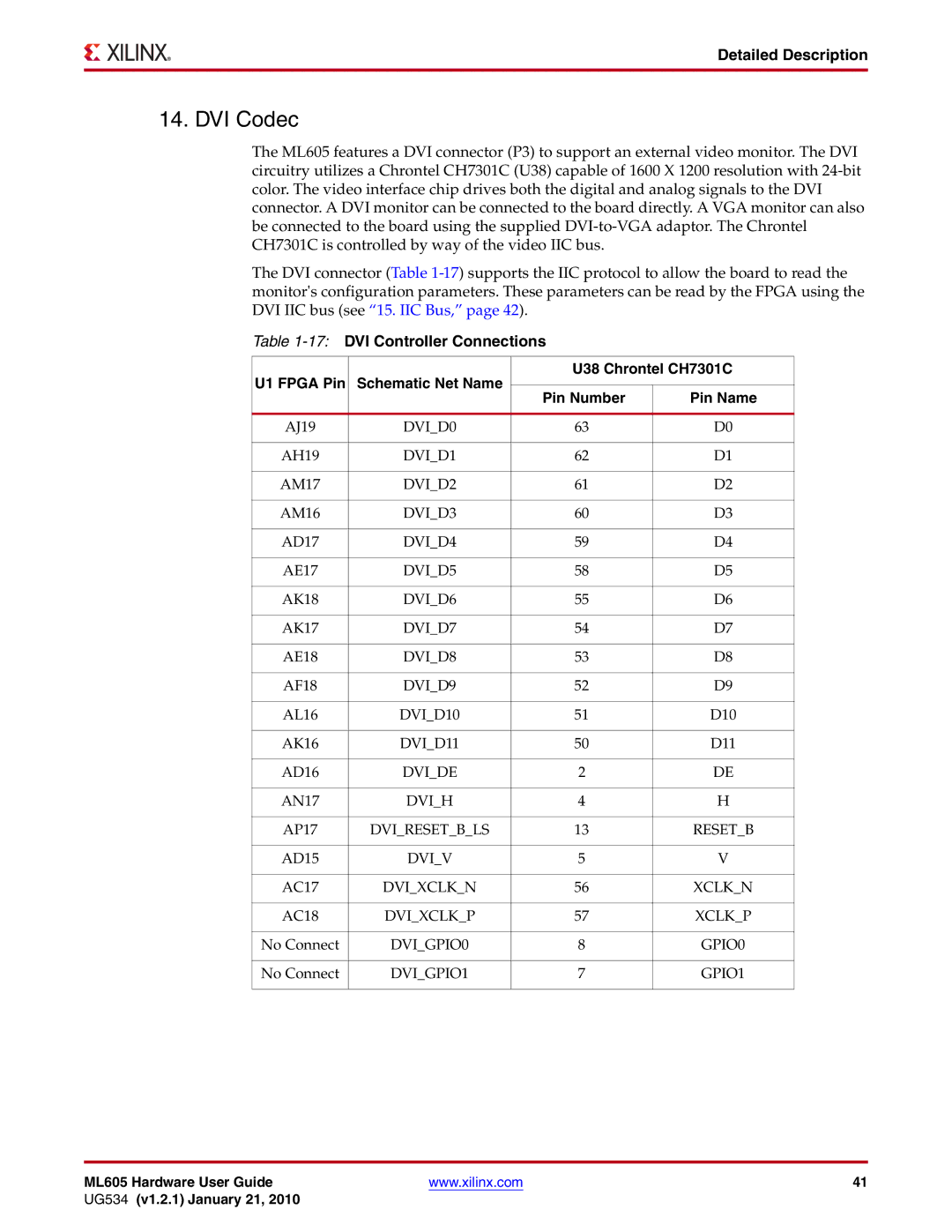
The ML605 features a DVI connector (P3) to support an external video monitor. The DVI circuitry utilizes a Chrontel CH7301C (U38) capable of 1600 X 1200 resolution with
The DVI connector (Table
Table 1-17: DVI Controller Connections
U1 FPGA Pin | Schematic Net Name | U38 Chrontel CH7301C | ||
|
| |||
Pin Number | Pin Name | |||
|
| |||
|
|
|
| |
AJ19 | DVI_D0 | 63 | D0 | |
|
|
|
| |
AH19 | DVI_D1 | 62 | D1 | |
|
|
|
| |
AM17 | DVI_D2 | 61 | D2 | |
|
|
|
| |
AM16 | DVI_D3 | 60 | D3 | |
|
|
|
| |
AD17 | DVI_D4 | 59 | D4 | |
|
|
|
| |
AE17 | DVI_D5 | 58 | D5 | |
|
|
|
| |
AK18 | DVI_D6 | 55 | D6 | |
|
|
|
| |
AK17 | DVI_D7 | 54 | D7 | |
|
|
|
| |
AE18 | DVI_D8 | 53 | D8 | |
|
|
|
| |
AF18 | DVI_D9 | 52 | D9 | |
|
|
|
| |
AL16 | DVI_D10 | 51 | D10 | |
|
|
|
| |
AK16 | DVI_D11 | 50 | D11 | |
|
|
|
| |
AD16 | DVI_DE | 2 | DE | |
|
|
|
| |
AN17 | DVI_H | 4 | H | |
|
|
|
| |
AP17 | DVI_RESET_B_LS | 13 | RESET_B | |
|
|
|
| |
AD15 | DVI_V | 5 | V | |
|
|
|
| |
AC17 | DVI_XCLK_N | 56 | XCLK_N | |
|
|
|
| |
AC18 | DVI_XCLK_P | 57 | XCLK_P | |
|
|
|
| |
No Connect | DVI_GPIO0 | 8 | GPIO0 | |
|
|
|
| |
No Connect | DVI_GPIO1 | 7 | GPIO1 | |
|
|
|
| |
ML605 Hardware User Guide | www.xilinx.com | 41 |
UG534 (v1.2.1) January 21, 2010 |
|
|