Detailed Description
18. Switches
The ML605 Evaluation board includes the following switches:
•Power On/Off Slide Switch SW2
•FPGA_PROG_B SW4
•SYSACE_RESET_B SW3
•System ACE CF CompactFlash Image Select DIP Switch S1
•MODE, Boot EEPROM Select and CCLK Osc Enable DIP switch S2
Power On/Off Slide Switch SW2
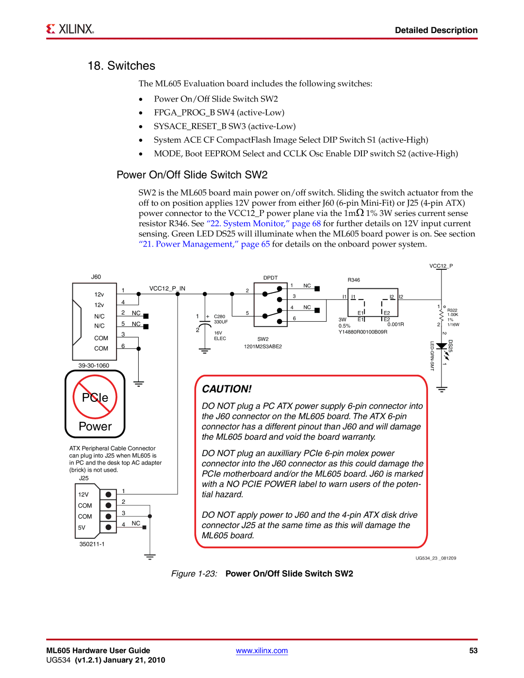
SW2 is the ML605 board main power on/off switch. Sliding the switch actuator from the off to on position applies 12V power from either J60
J60 |
|
|
|
|
|
|
|
|
|
|
| DPDT |
|
|
|
| R346 |
|
| |||
|
|
|
|
|
|
|
|
|
|
|
|
| 1 | NC |
|
|
|
|
| |||
|
| 1 |
|
|
|
|
|
|
| VCC12_P_IN |
|
|
|
|
|
|
| |||||
12v |
|
|
|
|
|
|
|
|
|
| 2 |
|
|
|
|
|
|
|
|
| ||
|
|
|
|
|
|
|
|
|
|
|
|
|
|
|
|
|
|
|
| |||
| 4 |
|
|
|
|
|
|
|
|
|
|
| 3 |
|
|
| I1 | I1 | I2 | I2 | ||
|
|
|
|
|
|
|
|
|
|
|
|
|
|
| ||||||||
12v |
|
|
|
|
|
|
|
|
|
| 4 | NC |
|
|
|
|
|
| ||||
2 | NC |
|
|
|
|
|
|
|
| E1 | E2 |
| ||||||||||
N/C |
|
| 1 |
| + C280 | 5 |
|
|
|
|
|
|
| |||||||||
|
|
|
|
|
|
|
|
|
| |||||||||||||
|
| 5 | NC |
|
|
|
| 330UF |
| 6 |
|
|
| 3W | E1 | E2 |
| |||||
N/C |
|
| 2 |
|
|
|
| 0.5% | 0.001R | |||||||||||||
COM | 3 |
|
|
|
|
|
|
| 16V |
|
|
|
|
|
| Y14880R00100B09R |
| |||||
|
|
|
|
|
|
|
|
|
|
|
|
|
|
|
| |||||||
|
|
|
|
|
|
|
|
| ELEC | SW2 |
|
|
|
|
|
|
| |||||
6 |
|
|
|
|
|
|
|
|
|
|
|
|
|
|
|
| ||||||
COM |
|
|
|
|
|
|
|
|
|
| 1201M2S3ABE2 |
|
|
|
|
|
|
| ||||
|
|
|
|
|
|
|
|
|
|
|
|
|
|
|
|
|
|
|
|
| ||
|
|
|
|
|
|
|
|
|
|
|
|
|
|
|
|
|
|
|
|
|
| |
|
|
|
|
|
|
|
|
|
|
|
|
|
|
|
|
|
|
|
|
|
|
|
|
|
|
|
|
|
|
|
|
|
|
|
|
|
|
|
|
|
|
|
|
|
|
PCIe |
|
|
|
|
|
| CAUTION! | |||
|
|
|
|
|
| DO NOT plug a PC ATX power supply | ||||
|
|
|
|
|
|
|
|
|
| |
Power |
|
|
|
|
|
| the J60 connector on the ML605 board. The ATX | |||
|
|
|
|
|
| connector has a different pinout than J60 and will damage | ||||
|
|
|
|
|
|
|
|
|
| the ML605 board and void the board warranty. |
ATX Peripheral Cable Connector | DO NOT plug an auxilliary PCIe | |||||||||
can plug into J25 when ML605 is | ||||||||||
in PC and the desk top AC adapter | connector into the J60 connector as this could damage the | |||||||||
(brick) is not used. |
|
|
|
|
|
| PCIe motherboard and/or the ML605 board. J60 is marked | |||
J25 |
|
|
|
|
|
| ||||
|
|
|
|
|
| with a NO PCIE POWER label to warn users of the poten- | ||||
|
|
|
| 1 |
|
|
|
|
| |
12V |
|
|
|
|
|
|
|
| tial hazard. | |
| 2 |
|
|
|
|
| ||||
COM |
|
|
|
|
|
|
| |||
| 3 |
|
|
|
|
| DO NOT apply power to J60 and the | |||
COM |
|
|
|
|
|
|
| |||
| 4 NC |
|
|
|
|
| ||||
5V |
|
|
|
|
| connector J25 at the same time as this will damage the | ||||
|
|
|
|
|
| |||||
|
|
|
| |||||||
|
|
|
|
|
|
|
| |||
|
|
|
|
|
|
|
|
|
| ML605 board. |
|
|
|
|
|
|
|
|
|
| |
|
|
|
|
|
|
|
|
|
|
|
VCC12_P
1
R322 1.00K
1%
21/16W
|
| 2 |
| |||
|
|
|
|
| DS25 | |
|
|
|
|
| ||
1 |
| |||||
|
|
|
|
|
|
|
|
|
|
|
|
|
|
UG534_23 _081209
Figure 1-23: Power On/Off Slide Switch SW2
ML605 Hardware User Guide | www.xilinx.com | 53 |
UG534 (v1.2.1) January 21, 2010 |
|
|