Detailed Description
System ACE CF CompactFlash Image Select DIP Switch S1
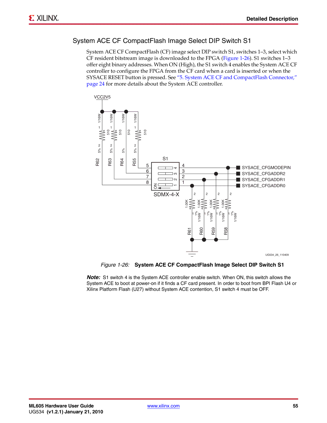
System ACE CF CompactFlash (CF) image select DIP switch S1, switches
VCC2V5
1/16W 1
2 5%
1/16W
1 510
2 5%
1/16W | 1/16W |
| 1 |
510 | 510 |
| 2 |
5% | 5% |
510
R62
3R6
R64 | R55 |
5
6
7
8
|
| S1 | |||
ON |
|
|
|
| 4 |
|
|
|
| ||
|
|
|
| ||
|
|
|
| 3 | |
|
|
|
| ||
|
|
|
| 2 | |
|
|
|
| ||
|
|
|
| 1 | |
|
|
| |||
|
|
|
|
| |
|
|
|
|
|
|
SDMX-4-X
4 | SYSACE_CFGMODEPIN | |
3 | ||
SYSACE_CFGADDR2 | ||
2 | ||
SYSACE_CFGADDR1 | ||
1 | ||
SYSACE_CFGADDR0 | ||
|
| 2 |
|
| 2 |
|
| 2 |
|
| 2 |
|
1.00K |
| 1.00K |
|
| 1.00K |
|
| 1.00K |
|
|
|
1 | 1% | 1/16W | 1 | 1% | 1/16W | 1 | 1% | 1/16W | 1 | 1% | 1/16W |
|
|
|
| ||||||||
R61 |
| R60 |
|
| R59 |
|
| R58 |
|
|
|
UG534_26_110409
Figure 1-26: System ACE CF CompactFlash Image Select DIP Switch S1
Note: S1 switch 4 is the System ACE controller enable switch. When ON, this switch allows the System ACE to boot at
ML605 Hardware User Guide | www.xilinx.com | 55 |
UG534 (v1.2.1) January 21, 2010 |
|
|
