PLB PCI Full Bridge (v1.00a)
Global Interrupt Enable Register Description
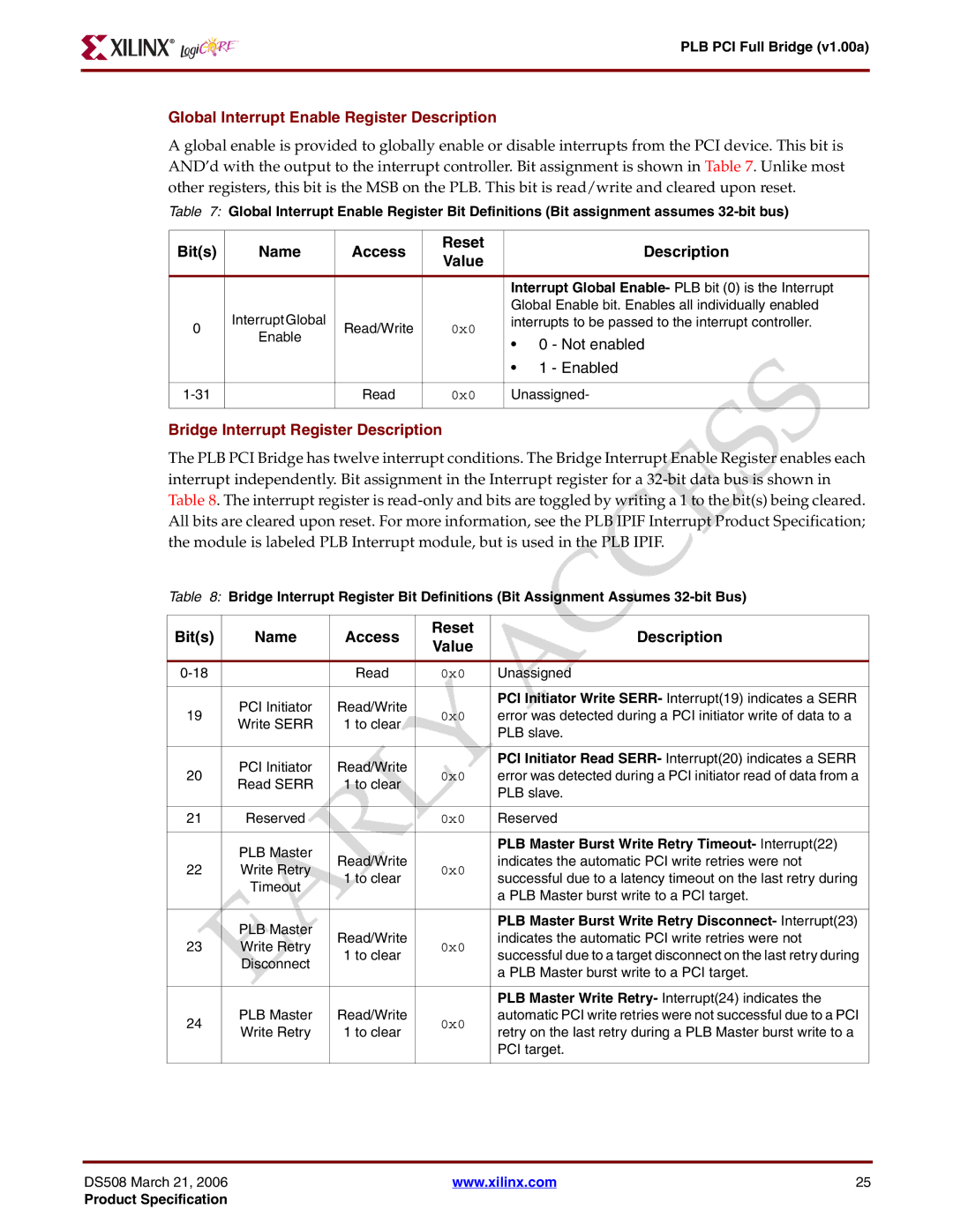
A global enable is provided to globally enable or disable interrupts from the PCI device. This bit is AND’d with the output to the interrupt controller. Bit assignment is shown in Table 7. Unlike most other registers, this bit is the MSB on the PLB. This bit is read/write and cleared upon reset.
Table 7: Global Interrupt Enable Register Bit Definitions (Bit assignment assumes
Bit(s) | Name | Access | Reset |
| Description | |
Value |
| |||||
|
|
|
|
| ||
|
|
|
|
| ||
|
|
|
| Interrupt Global Enable- PLB bit (0) is the Interrupt | ||
| Interrupt Global |
|
| Global Enable bit. Enables all individually enabled | ||
0 | Read/Write | 0x0 | interrupts to be passed to the interrupt controller. | |||
Enable | • | 0 - Not enabled | ||||
|
|
| ||||
|
|
|
| |||
|
|
|
| • | 1 - Enabled | |
|
|
|
|
| ||
| Read | 0x0 | Unassigned- | |||
|
|
|
|
|
| |
Bridge Interrupt Register Description
The PLB PCI Bridge has twelve interrupt conditions. The Bridge Interrupt Enable Register enables each interrupt independently. Bit assignment in the Interrupt register for a
Table 8: Bridge Interrupt Register Bit Definitions (Bit Assignment Assumes
Bit(s) | Name | Access | Reset | Description | |
Value | |||||
|
|
|
| ||
|
|
|
|
| |
| Read | 0x0 | Unassigned | ||
|
|
|
|
| |
| PCI Initiator | Read/Write |
| PCI Initiator Write SERR- Interrupt(19) indicates a SERR | |
19 | 0x0 | error was detected during a PCI initiator write of data to a | |||
Write SERR | 1 to clear | ||||
|
| PLB slave. | |||
|
|
|
| ||
|
|
|
|
| |
| PCI Initiator | Read/Write |
| PCI Initiator Read SERR- Interrupt(20) indicates a SERR | |
20 | 0x0 | error was detected during a PCI initiator read of data from a | |||
Read SERR | 1 to clear | ||||
|
| PLB slave. | |||
|
|
|
| ||
|
|
|
|
| |
21 | Reserved |
| 0x0 | Reserved | |
|
|
|
|
| |
| PLB Master |
|
| PLB Master Burst Write Retry Timeout- Interrupt(22) | |
| Read/Write |
| indicates the automatic PCI write retries were not | ||
22 | Write Retry | 0x0 | |||
1 to clear | successful due to a latency timeout on the last retry during | ||||
| Timeout |
| |||
|
|
| a PLB Master burst write to a PCI target. | ||
|
|
|
| ||
|
|
|
|
| |
| PLB Master |
|
| PLB Master Burst Write Retry Disconnect- Interrupt(23) | |
| Read/Write |
| indicates the automatic PCI write retries were not | ||
23 | Write Retry | 0x0 | |||
1 to clear | successful due to a target disconnect on the last retry during | ||||
| Disconnect |
| |||
|
|
| a PLB Master burst write to a PCI target. | ||
|
|
|
| ||
|
|
|
|
| |
|
|
|
| PLB Master Write Retry- Interrupt(24) indicates the | |
24 | PLB Master | Read/Write | 0x0 | automatic PCI write retries were not successful due to a PCI | |
Write Retry | 1 to clear | retry on the last retry during a PLB Master burst write to a | |||
|
| ||||
|
|
|
| PCI target. | |
|
|
|
|
|
DS508 March 21, 2006 | www.xilinx.com | 25 |
Product Specification