PLB PCI Full Bridge (v1.00a)
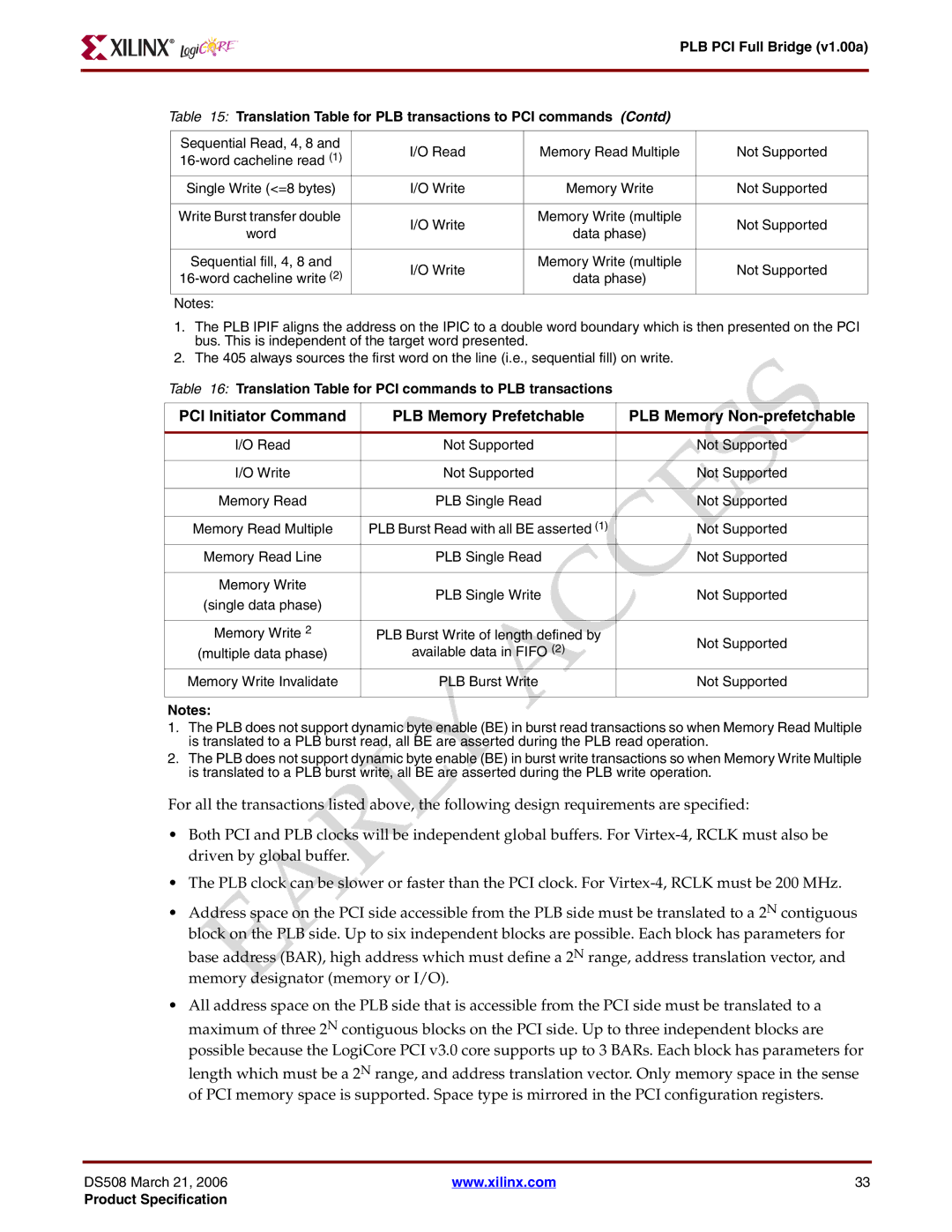
Table 15: Translation Table for PLB transactions to PCI commands (Contd)
Sequential Read, 4, 8 and | I/O Read | Memory Read Multiple | Not Supported | |
|
|
| ||
Single Write (<=8 bytes) | I/O Write | Memory Write | Not Supported | |
|
|
|
| |
Write Burst transfer double | I/O Write | Memory Write (multiple | Not Supported | |
word | data phase) | |||
|
| |||
|
|
|
| |
Sequential fill, 4, 8 and | I/O Write | Memory Write (multiple | Not Supported | |
data phase) | ||||
|
| |||
Notes: |
|
|
|
1.The PLB IPIF aligns the address on the IPIC to a double word boundary which is then presented on the PCI bus. This is independent of the target word presented.
2.The 405 always sources the first word on the line (i.e., sequential fill) on write.
Table 16: Translation Table for PCI commands to PLB transactions
PCI Initiator Command | PLB Memory Prefetchable | PLB Memory | |
|
|
| |
I/O Read | Not Supported | Not Supported | |
|
|
| |
I/O Write | Not Supported | Not Supported | |
|
|
| |
Memory Read | PLB Single Read | Not Supported | |
|
|
| |
Memory Read Multiple | PLB Burst Read with all BE asserted (1) | Not Supported | |
Memory Read Line | PLB Single Read | Not Supported | |
|
|
| |
Memory Write | PLB Single Write | Not Supported | |
(single data phase) | |||
|
| ||
|
|
| |
Memory Write 2 | PLB Burst Write of length defined by | Not Supported | |
(multiple data phase) | available data in FIFO (2) | ||
| |||
Memory Write Invalidate | PLB Burst Write | Not Supported | |
|
|
|
Notes:
1.The PLB does not support dynamic byte enable (BE) in burst read transactions so when Memory Read Multiple is translated to a PLB burst read, all BE are asserted during the PLB read operation.
2.The PLB does not support dynamic byte enable (BE) in burst write transactions so when Memory Write Multiple is translated to a PLB burst write, all BE are asserted during the PLB write operation.
For all the transactions listed above, the following design requirements are specified:
•Both PCI and PLB clocks will be independent global buffers. For
•The PLB clock can be slower or faster than the PCI clock. For
•Address space on the PCI side accessible from the PLB side must be translated to a 2N contiguous block on the PLB side. Up to six independent blocks are possible. Each block has parameters for base address (BAR), high address which must define a 2N range, address translation vector, and memory designator (memory or I/O).
•All address space on the PLB side that is accessible from the PCI side must be translated to a maximum of three 2N contiguous blocks on the PCI side. Up to three independent blocks are possible because the LogiCore PCI v3.0 core supports up to 3 BARs. Each block has parameters for length which must be a 2N range, and address translation vector. Only memory space in the sense of PCI memory space is supported. Space type is mirrored in the PCI configuration registers.
DS508 March 21, 2006 | www.xilinx.com | 33 |
Product Specification