PLB PCI Full Bridge (v1.00a)
System Reset
When the bridge is reset, both RST_N and PLB_reset must be simultaneously held at reset for at least twenty clock periods of the slowest clock.
Evaluation Version
The PLB PCI Bridge is delivered with a hardware evaluation license. When programmed into a Xilinx device, the core will function in hardware for about 8 hours at the typical frequency of operation. To use the PLB PCI Bridge without this timeout limitation, a full license must be purchased.
Functional Description
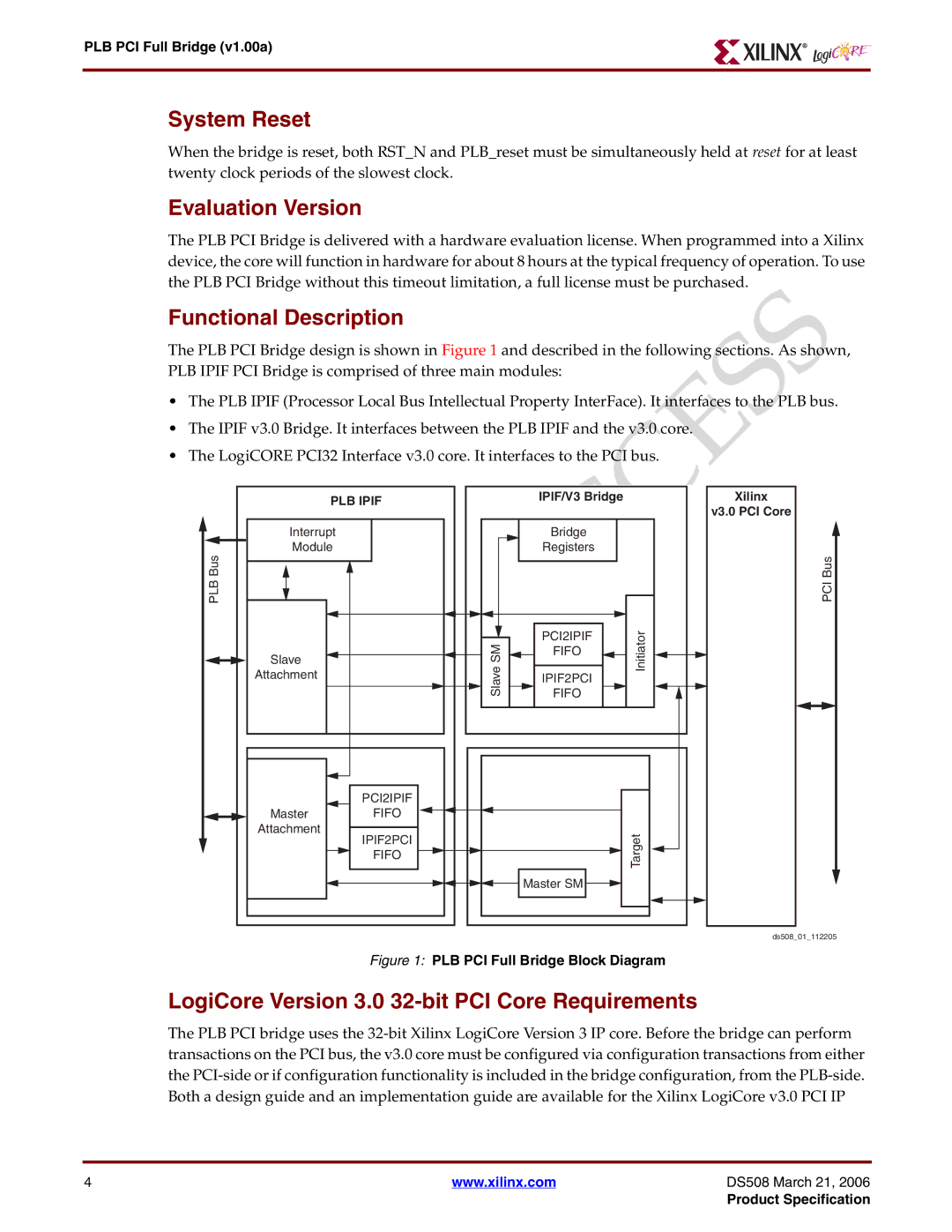
The PLB PCI Bridge design is shown in Figure 1 and described in the following sections. As shown, PLB IPIF PCI Bridge is comprised of three main modules:
•The PLB IPIF (Processor Local Bus Intellectual Property InterFace). It interfaces to the PLB bus.
•The IPIF v3.0 Bridge. It interfaces between the PLB IPIF and the v3.0 core.
•The LogiCORE PCI32 Interface v3.0 core. It interfaces to the PCI bus.
PLB IPIF | IPIF/V3 Bridge |
| |
|
| ||
Interrupt |
| Bridge |
|
Module |
| Registers |
|
Bus |
|
|
|
PLB |
|
|
|
| ave SM | PCI2IPIF | Initiator |
Slave | FIFO | ||
| |||
Attachment | IPIF2PCI | ||
| Sl | FIFO |
|
|
|
| |
| PCI2IPIF |
|
|
Master | FIFO |
|
|
Attachment | IPIF2PCI |
| Target |
|
| ||
| FIFO |
| |
|
|
| |
|
| Master SM |
|
Figure 1: PLB PCI Full Bridge Block Diagram
Xilinx
v3.0 PCI Core
PCI Bus
ds508_01_112205
LogiCore Version 3.0 32-bit PCI Core Requirements
The PLB PCI bridge uses the
4 | www.xilinx.com | DS508 March 21, 2006 |
|
| Product Specification |
