Printer Frame, QL220/220Plus- AN16972-001
You must use an ESD strap and work at a properly grounded workstation (antistatic mat or tray). All electronic components must be placed on an ESD protective tray. If stored, any elec- tronic components must be placed in antistatic bags.
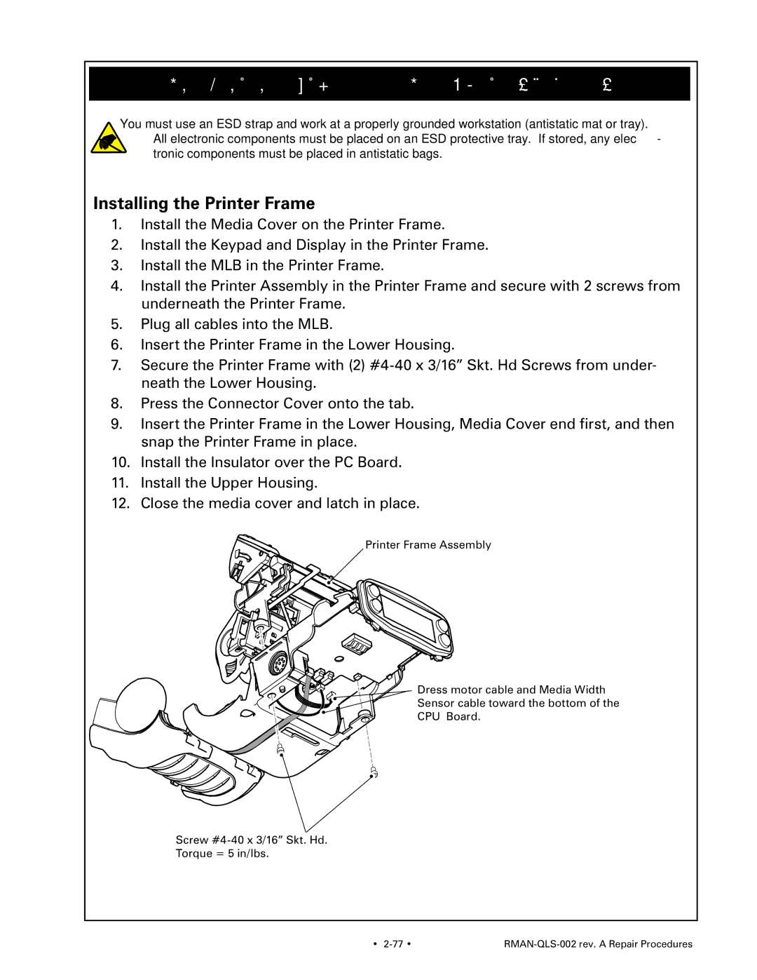
Installing the Printer Frame
1.Install the Media Cover on the Printer Frame.
2.Install the Keypad and Display in the Printer Frame.
3.Install the MLB in the Printer Frame.
4.Install the Printer Assembly in the Printer Frame and secure with 2 screws from underneath the Printer Frame.
5.Plug all cables into the MLB.
6.Insert the Printer Frame in the Lower Housing.
7.Secure the Printer Frame with (2)
8.Press the Connector Cover onto the tab.
9.Insert the Printer Frame in the Lower Housing, Media Cover end first, and then snap the Printer Frame in place.
10.Install the Insulator over the PC Board.
11.Install the Upper Housing.
12.Close the media cover and latch in place.
Printer Frame Assembly
Dress motor cable and Media Width
Sensor cable toward the bottom of the
CPU Board.
Screw
Torque = 5 in/lbs.
• |
|