Mobile Printers
Proprietary Statement
Product Improvements
Contents
QL series configurations and Parts
Description
Operating Modes
Printing Technology
Communications
Diagnostic Tools
Introduction to Label Vista
Sample Configuration Label
Printing a Diagnostic Label
Creating a Configuration Label
Peripherals installed
Configuration Label Example
Starting Label Vista
Using Label Vista
Equipment Required For Label Vista
Equipment Required
Running The Software
Additional information
Using the QL Product Configuration Code
QL Component Replacement Procedures
Optional LCD Control Panel
Troubleshooting
Standard Control Panel
Troubleshooting Topics
No power
Poor or faded print or flashing
RMAN-QLS-002 rev. a Repair Procedures
QL220/220 Plus Repair Path
QL320 & QL420 Repair Path
MLB
Tools and Supplies
Storage and Handling
Installing the Media Cover
Media Cover, QL 220- RK18236-1 & QL220 Plus- RK17735-015
Tools Needed
Removing the Media Cover
RMAN-QLS-002 rev. a Repair Procedures
Media Cover, QL 320, QL 320 Plus & QL 420,QL 420 Plus
Model Kit p/n Comments
Installing the Media Cover
RMAN-QLS-002 rev. a Repair Procedures
Media Guide Plate Assembly, QL220/220 Plus
Removing the Media Guide Plate Assembly
Installing the Media Guide Plate Assembly
Installing the Media Assembly
Media Guide Assembly, QL320/320 Plus
Removing the Media Assembly
Ensure Media Sensor cable is behind holding feature
Media Guide Assembly, QL420/420 Plus
Kit p/n Description Type
Module
Remove the Media Support Disks
Install new Media Support Disks
Media Support Disks, QL Series
Changing the Media Core Size
Changing Media type
Media Guide Rollers, QL420/QL 420 Plus AN16753-003
Replacing the Media Rollers
Installing the Gear and Platen
AN16792-008- Installing the Peeler Bar
AN16792-009- Installing the Scraper
Platen/Gear Kits, QL220/QL 220 Plus AN16972-008
Installing the Scraper
Platen/Gear Kits, QL320/320 Plus- AN16861-013 & AN16861 014
Replacing the Platen Assembly
Platen/Gear Kits, QL420/420 Plus- AN16753-021
Introduction
Preparation
Remove the old Platen Assembly
Upper Housing /Wireless Modules-QL220 & QL 220 Plus
Removing the Upper Housing
Installing the Upper Housing
Set New Parameters
Upper Housing, QL320- RK18233-1
Installing the Upper Housing
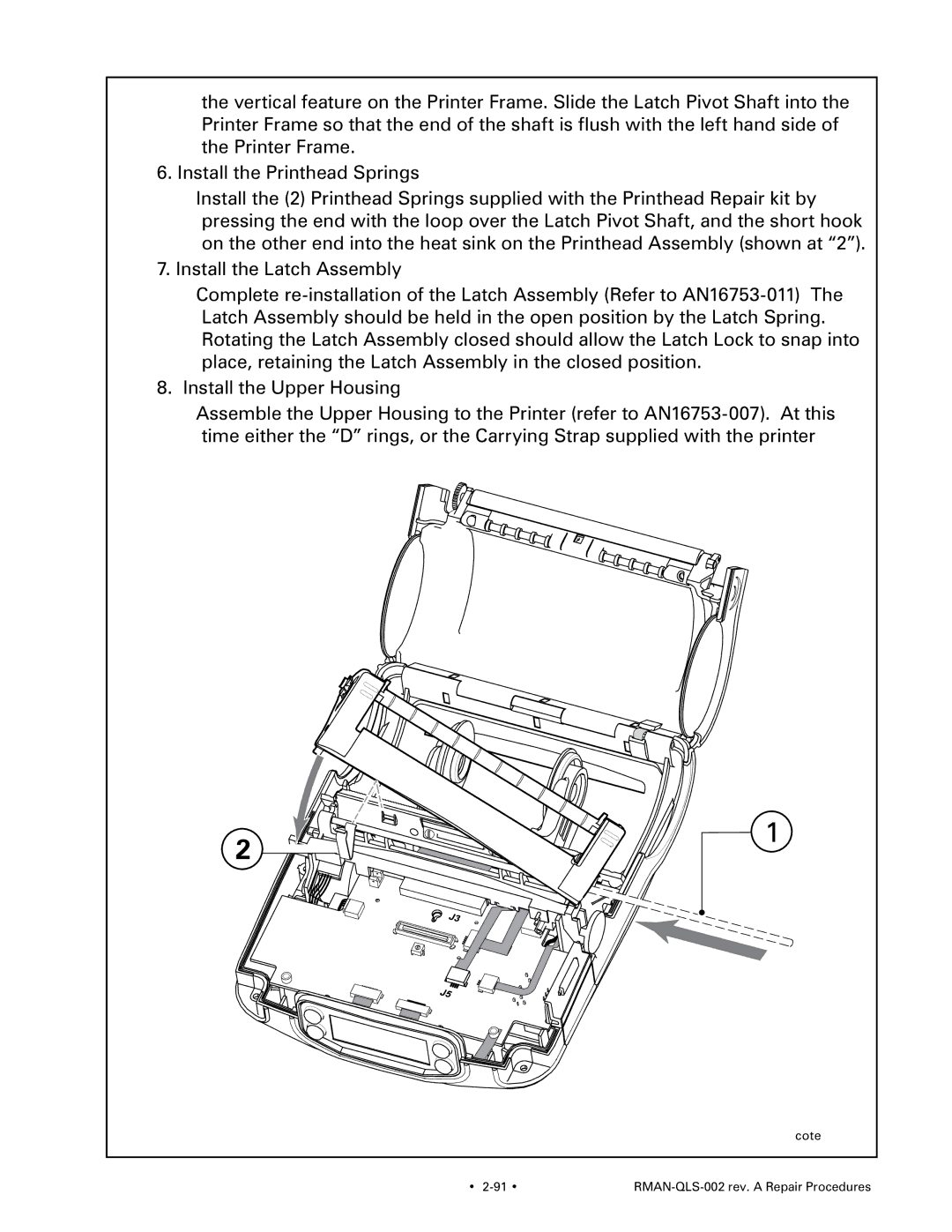
Upper Housing, QL420/420 Plus- AN16753-007
Assemble the P.C. Board Cover
Housing, Upper p/n DA16394-1
Assemble P.C. Board Cover
Install the Upper Housing
Assemble the Sensor Support
Remove the Upper Housing
Label Presence Sensor, QL320- AN16861-015
Install Label Present Sensor Option
Re-install the Upper Housing
Installing a Wlan Radio and Antenna
Install the Radio
Finish the Assembly
Assemble the Antenna
QL 320/320 Plus & QL 420/420 Plus Wireless Modules
Procedure Outline
Removing the Wireless Module
Installing the Wireless Module
Upper Housing or Wireless Module Screw, #4-40 x 3/8
Removing the LCD module
Installing the Keypad
Removing the Keypad
Installing the LCD module
Installing an LCD Keypad
Installing a Membrane Key Pad
Installing the Printer Frame
Printer Frame, QL220/220Plus- AN16972-001
Install the new Printer Frame Assembly
Removing the Printer Frame
RMAN-QLS-002 rev. a Repair Procedures
From # of connections CPU Connector #
Connector Door, QL 220 /QL220 Plus AN16972-021
Remove the Connector Door
Attach the new Connector Door
Remove the Lower Cover
Connector Door, QL420 & QL420 Plus- AN16753-020
Install the Connector Door
Installing the Motor
Motor,QL220 & QL 220 Plus AN16972-002
Motor, QL 320/320 Plus & QL420/420 Plus- RK18251-1
Removing the Motor
From # of connections CPU Connector #
Installing the Printhead
Printhead, QL220- RK18278-1 & QL 220 Plus- RK17735-016
Printhead, QL320 RK18277-1 & QL 320 Plus- RK18465-003
Remove the Printhead
Install the new Printhead Assembly
Printhead, QL 420- RK18252-1 & QL 420 Plus- RK17735-004
RMAN-QLS-002 rev. a Repair Procedures
RMAN-QLS-002 rev. a Repair Procedures
RMAN-QLS-002 rev. a Repair Procedures
RMAN-QLS-002 rev. a Repair Procedures
Installing the Latch
Latch, QL 220/QL 220 Plus- AN16972-004
RMAN-QLS-002 rev. a Repair Procedures
Latch, QL 320/ QL 320 Plus- AN16861-025
Latch, QL 420/ QL 420 Plus- AN16753-011
Removing the Latch
Latch Assembly
Installing the Peeler Shaft and Roller
Removing the Peeler Shaft and Roller
Installing the MLB
Removing the MLB
From # of connections MLB Connector #
Compatibility Switch SW1
J4 Motor
103 RMAN-QLS-002 rev. a Repair Procedures
RMAN-QLS-002 rev. a Repair Procedures 104
105 RMAN-QLS-002 rev. a Repair Procedures
RMAN-QLS-002 rev. a Repair Procedures 106
Installing the Belt Clip
Removing the Belt Clip
QL220 QL320
QL420
AN16753-010 Install the D-Rings
AN16753-009 Install the Carrying Strap
Installing the D Rings
Installing the Bushings
Removing the D Rings
Removing the Bushings
Install the Kickstand QL 220 ilustrated
Removing the Battery Pack
Installing the Battery Pack
Using the Product Configuration Code
Component Replacement Procedures
Europe
Factory Repair and Parts Ordering Procedure
Repair Services contact Information USA
QL 220 Product Configuration Code PCC
PCC Notes
Accessory Parts not illustrated
PCC Example
QL 220 & 220 Plus Replacement Kits
KIT RPR QL2 Media Guide W/BELT
Shaded items are not illustrated
QL 220 & 220 Plus Parts
Printer Mechanism Exploded View
QL 220 & 220 Plus Parts- Unit Exploded View
QL 320 & 320 Plus Product Configuration Code
PCC
Interpreting the PCC Code
QL 320 & 320 Plus Replacement Kits
Assy Module Irda QL3/4 QL
KIT RPR QL 320 Media GUIDE/MW
Unit Exploded View
Pcmcia Radio Options
QL 420 & 420 Plus Product Configuration Code
Parts Not Illustrated
QL 420 & 420 Plus Replacement Kits
KIT Repair QL4 PRINTHD/SENSOR
Self TAP SCREW, M3X6, QTY
RMAN-QLS-002 rev. a Replacement Kits 130
Pcmcia Option