Front Panel |
| WARNING: Use only a nonconductive object such as a plastic stylus to |
| press the hardware interrupt switch. Do not use the tip of a pencil. |
| Graphite particles can cause electrical shock to the operator and can |
| damage components on the server’s circuit boards. |
Cover | The inverted |
| edge of each side of the chassis. |
| Both sides of the cover have vents. The vents on the left side (viewed |
| from the front of the server) are for air intake. The vents on the right |
| side are for air exhaust. |
|
|
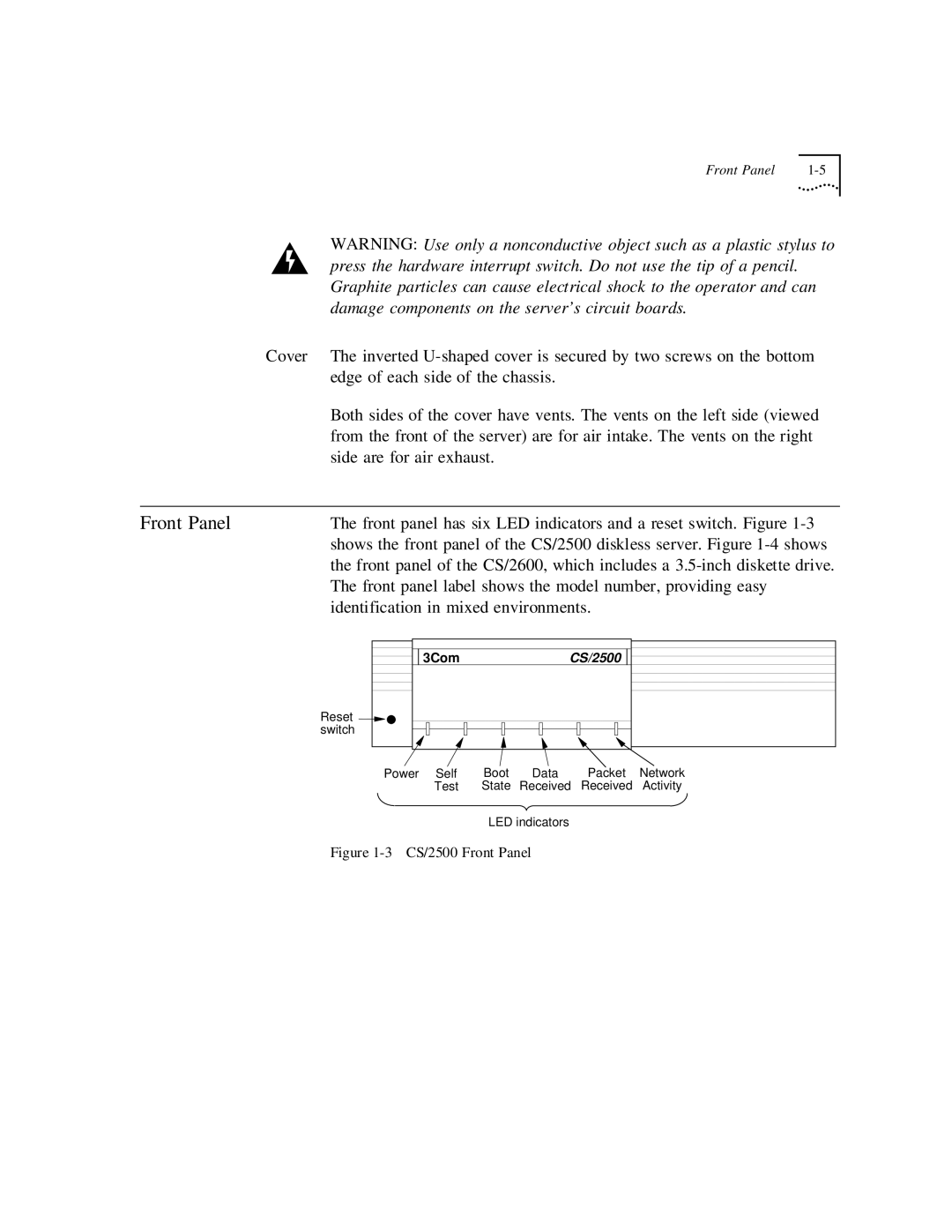
Front Panel | The front panel has six LED indicators and a reset switch. Figure |
| shows the front panel of the CS/2500 diskless server. Figure |
| the front panel of the CS/2600, which includes a |
| The front panel label shows the model number, providing easy |
| identification in mixed environments. |
Reset ![]()
![]() switch
switch
3Com | CS/2500 |
Power Self | Boot | Data | Packet | Network |
Test | State | Received | Received | Activity |
LED indicators