Parallel Printer Port |
Table
Pin | Function | Circuit | Use |
|
|
|
|
11* | Transmit Shield |
| Data Out circuit shield |
12 | Receive |
| Data In circuit B |
13† | Power | VP | Voltage plus |
14* | Power Shield | VS | Voltage shield |
15 | Control Out |
| Control Out circuit B |
Shell | Chassis Ground | PG | Protective ground; |
|
|
| conductive shell |
* Attached to power return.
† Current should not exceed 500 mA.
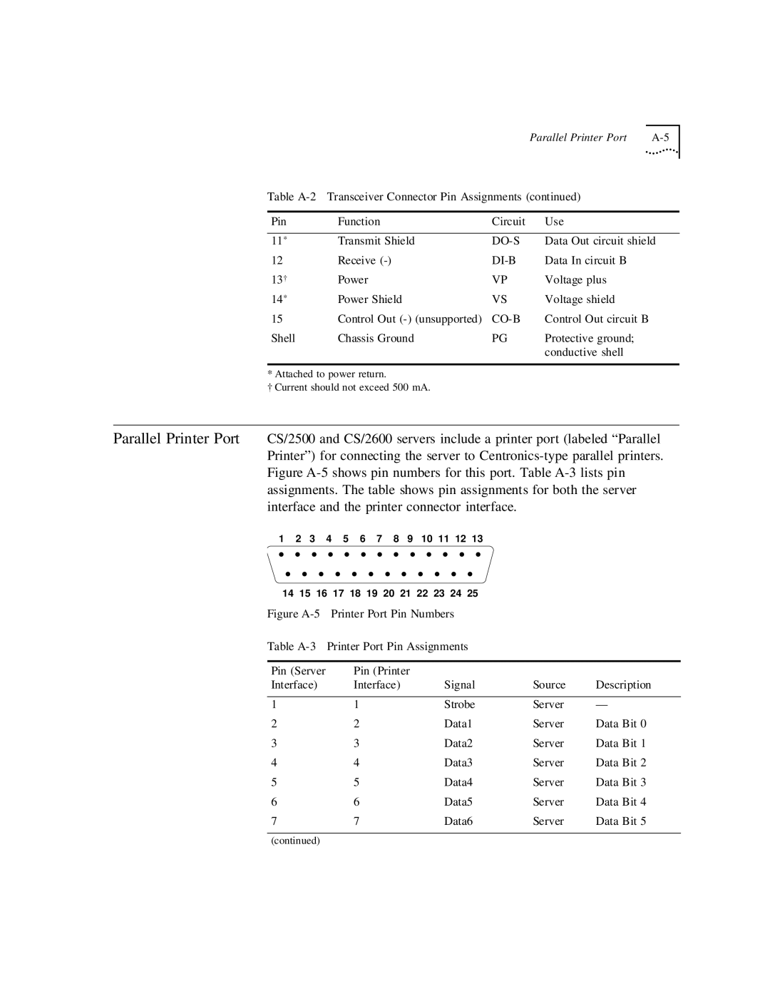
Parallel Printer Port CS/2500 and CS/2600 servers include a printer port (labeled “Parallel Printer”) for connecting the server to
1 2 3 4 5 6 7 8 9 10 11 12 13
• • • • • • • • • • • • •
• • • • • • • • • • • •
14 15 16 17 18 19 20 21 22 23 24 25
Figure A-5 Printer Port Pin Numbers
Table A-3 Printer Port Pin Assignments
Pin (Server | Pin (Printer |
|
|
|
Interface) | Interface) | Signal | Source | Description |
|
|
|
|
|
1 | 1 | Strobe | Server | — |
2 | 2 | Data1 | Server | Data Bit 0 |
3 | 3 | Data2 | Server | Data Bit 1 |
4 | 4 | Data3 | Server | Data Bit 2 |
5 | 5 | Data4 | Server | Data Bit 3 |
6 | 6 | Data5 | Server | Data Bit 4 |
7 | 7 | Data6 | Server | Data Bit 5 |
(continued)