DCE
CS/2500 Pin
13 | TXD+ |
| |
14 | TXD- |
| |
16 | RXD- |
| |
19 | RXD+ |
| |
22 |
|
25 |
|
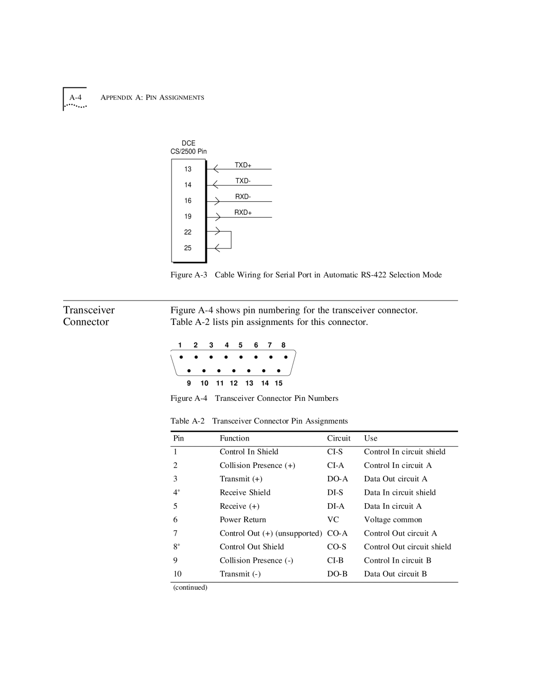
Figure A-3 Cable Wiring for Serial Port in Automatic RS-422 Selection Mode
Transceiver | Figure | |||||||
Connector | Table | |||||||
| 1 | 2 | 3 | 4 | 5 | 6 | 7 | 8 |
| • | • | • | • | • | • | • | • |
| • | • | • | • | • |
| • | • |
| 9 | 10 | 11 | 12 | 13 |
| 14 | 15 |
| Figure | |||||||
| Table | Transceiver Connector Pin Assignments | ||||||
Pin | Function | Circuit | Use |
|
|
|
|
1 | Control In Shield | Control In circuit shield | |
2 | Collision Presence (+) | Control In circuit A | |
3 | Transmit (+) | Data Out circuit A | |
4* | Receive Shield | Data In circuit shield | |
5 | Receive (+) | Data In circuit A | |
6 | Power Return | VC | Voltage common |
7 | Control Out (+) (unsupported) | Control Out circuit A | |
8* | Control Out Shield | Control Out circuit shield | |
9 | Collision Presence | Control In circuit B | |
10 | Transmit |
| Data Out circuit B |
(continued)
