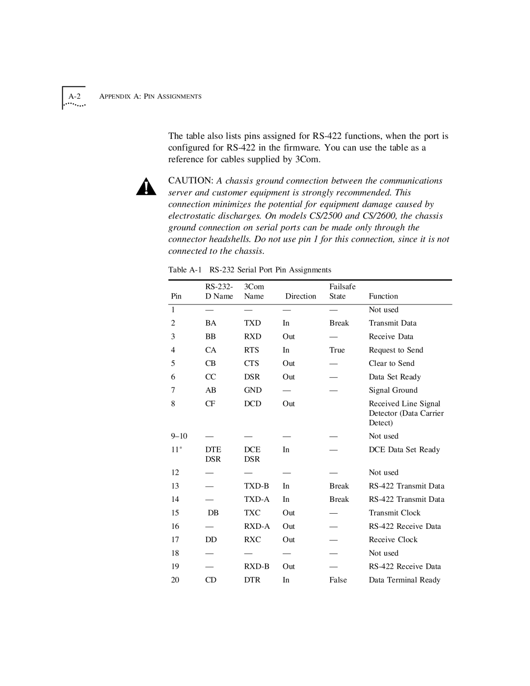
The table also lists pins assigned for
CAUTION: A chassis ground connection between the communications server and customer equipment is strongly recommended. This connection minimizes the potential for equipment damage caused by electrostatic discharges. On models CS/2500 and CS/2600, the chassis ground connection on serial ports can be made only through the connector headshells. Do not use pin 1 for this connection, since it is not connected to the chassis.
Table
| 3Com |
| Failsafe |
| |
Pin | D Name | Name | Direction | State | Function |
|
|
|
|
|
|
1 | — | — | — | — | Not used |
2 | BA | TXD | In | Break | Transmit Data |
3 | BB | RXD | Out | — | Receive Data |
4 | CA | RTS | In | True | Request to Send |
5 | CB | CTS | Out | — | Clear to Send |
6 | CC | DSR | Out | — | Data Set Ready |
7 | AB | GND | — | — | Signal Ground |
8 | CF | DCD | Out |
| Received Line Signal |
|
|
|
|
| Detector (Data Carrier |
|
|
|
|
| Detect) |
— | — | — | — | Not used | |
11* | DTE | DCE | In | — | DCE Data Set Ready |
| DSR | DSR |
|
|
|
12 | — | — | — | — | Not used |
13 | — | In | Break | ||
14 | — | In | Break | ||
15 | DB | TXC | Out | — | Transmit Clock |
16 | — | Out | — | ||
17 | DD | RXC | Out | — | Receive Clock |
18 | — | — | — | — | Not used |
19 | — | Out | — | ||
20 | CD | DTR | In | False | Data Terminal Ready |