Back Panel |
Reset Switch The reset switch is located at the lower left corner of the front panel (see Figure
CS/2600 Internal Model CS/2600 includes a
accommodate 1 MB or 2 MB unformatted capacity (720 KB or 1.44 MB formatted) diskettes. This drive is used for booting system software and for performing memory dumps following a server failure. The diskette is also used during operation to maintain software configuration information.
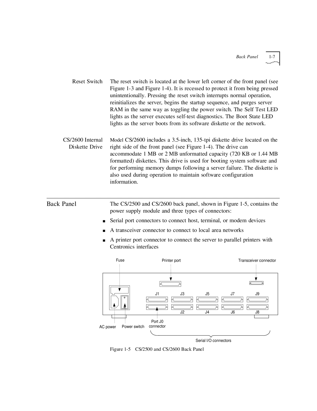
Back Panel | The CS/2500 and CS/2600 back panel, shown in Figure |
| power supply module and three types of connectors: |
■Serial port connectors to connect host, terminal, or modem devices
■A transceiver connector to connect to local area networks
■A printer port connector to connect the server to parallel printers with Centronics interfaces
Fuse | Printer port |
|
| Transceiver connector |
J1 | J3 | J5 | J7 | J9 |
| J2 | J4 | J6 | J8 |
Port J0
AC power Power switch connector
Serial I/O connectors