| 3Com |
|
| CS/2600 |
|
|
|
Reset |
|
|
|
|
|
|
|
switch |
|
|
|
|
|
|
|
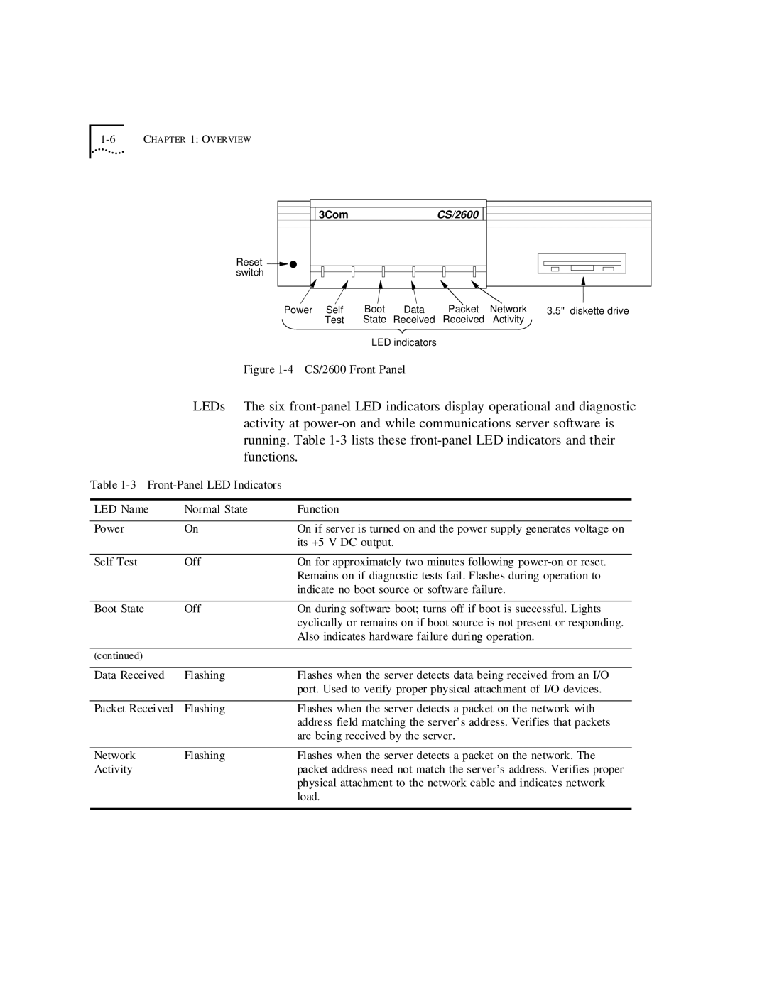
Power | Self | Boot | Data | Packet | Network | 3.5" | diskette drive |
| Test | State | Received | Received | Activity |
|
|
|
| LED indicators |
|
|
|
| |
Figure 1-4 CS/2600 Front Panel
LEDs The six
Table
LED Name | Normal State | Function |
|
|
|
Power | On | On if server is turned on and the power supply generates voltage on |
|
| its +5 V DC output. |
|
|
|
Self Test | Off | On for approximately two minutes following |
|
| Remains on if diagnostic tests fail. Flashes during operation to |
|
| indicate no boot source or software failure. |
|
|
|
Boot State | Off | On during software boot; turns off if boot is successful. Lights |
|
| cyclically or remains on if boot source is not present or responding. |
|
| Also indicates hardware failure during operation. |
|
|
|
(continued) |
|
|
|
|
|
Data Received | Flashing | Flashes when the server detects data being received from an I/O |
|
| port. Used to verify proper physical attachment of I/O devices. |
|
|
|
Packet Received | Flashing | Flashes when the server detects a packet on the network with |
|
| address field matching the server’s address. Verifies that packets |
|
| are being received by the server. |
|
|
|
Network | Flashing | Flashes when the server detects a packet on the network. The |
Activity |
| packet address need not match the server’s address. Verifies proper |
|
| physical attachment to the network cable and indicates network |
|
| load. |
|
|
|