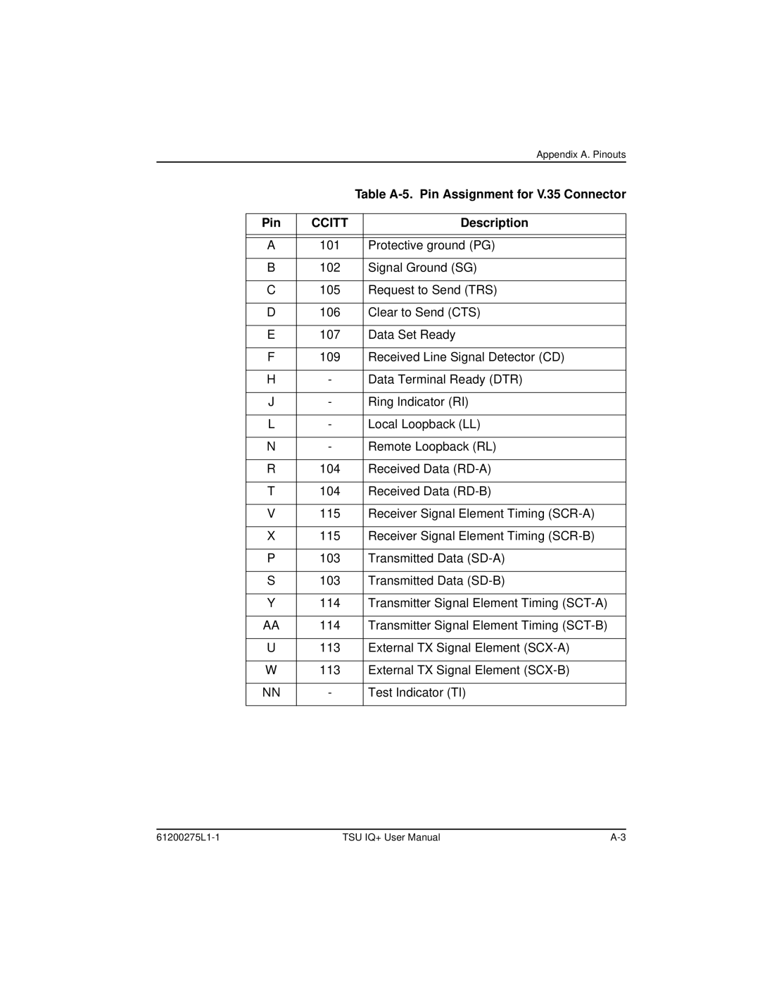
Appendix A. Pinouts
|
| Table | |
|
|
|
|
Pin | CCITT |
| Description |
|
|
|
|
|
|
|
|
A | 101 |
| Protective ground (PG) |
|
|
|
|
B | 102 |
| Signal Ground (SG) |
|
|
|
|
C | 105 |
| Request to Send (TRS) |
|
|
|
|
D | 106 |
| Clear to Send (CTS) |
|
|
|
|
E | 107 |
| Data Set Ready |
|
|
|
|
F | 109 |
| Received Line Signal Detector (CD) |
|
|
|
|
H | - |
| Data Terminal Ready (DTR) |
|
|
|
|
J | - |
| Ring Indicator (RI) |
|
|
|
|
L | - |
| Local Loopback (LL) |
|
|
|
|
N | - |
| Remote Loopback (RL) |
|
|
|
|
R | 104 |
| Received Data |
|
|
|
|
T | 104 |
| Received Data |
|
|
|
|
V | 115 |
| Receiver Signal Element Timing |
|
|
|
|
X | 115 |
| Receiver Signal Element Timing |
|
|
|
|
P | 103 |
| Transmitted Data |
|
|
|
|
S | 103 |
| Transmitted Data |
|
|
|
|
Y | 114 |
| Transmitter Signal Element Timing |
|
|
|
|
AA | 114 |
| Transmitter Signal Element Timing |
|
|
|
|
U | 113 |
| External TX Signal Element |
|
|
|
|
W | 113 |
| External TX Signal Element |
|
|
|
|
NN | - |
| Test Indicator (TI) |
|
|
|
|
TSU IQ+ User Manual |