|
|
|
|
| Ref.: |
|
| |
|
|
|
| SpaceWire Router |
| UserManual |
| |
|
|
|
| Issue: | 3.4 |
|
| |
|
|
|
| User Manual |
|
| ||
|
|
|
| Date: | 11th July 2008 |
| ||
|
|
|
|
|
|
|
|
|
|
|
|
|
|
|
|
| |
|
|
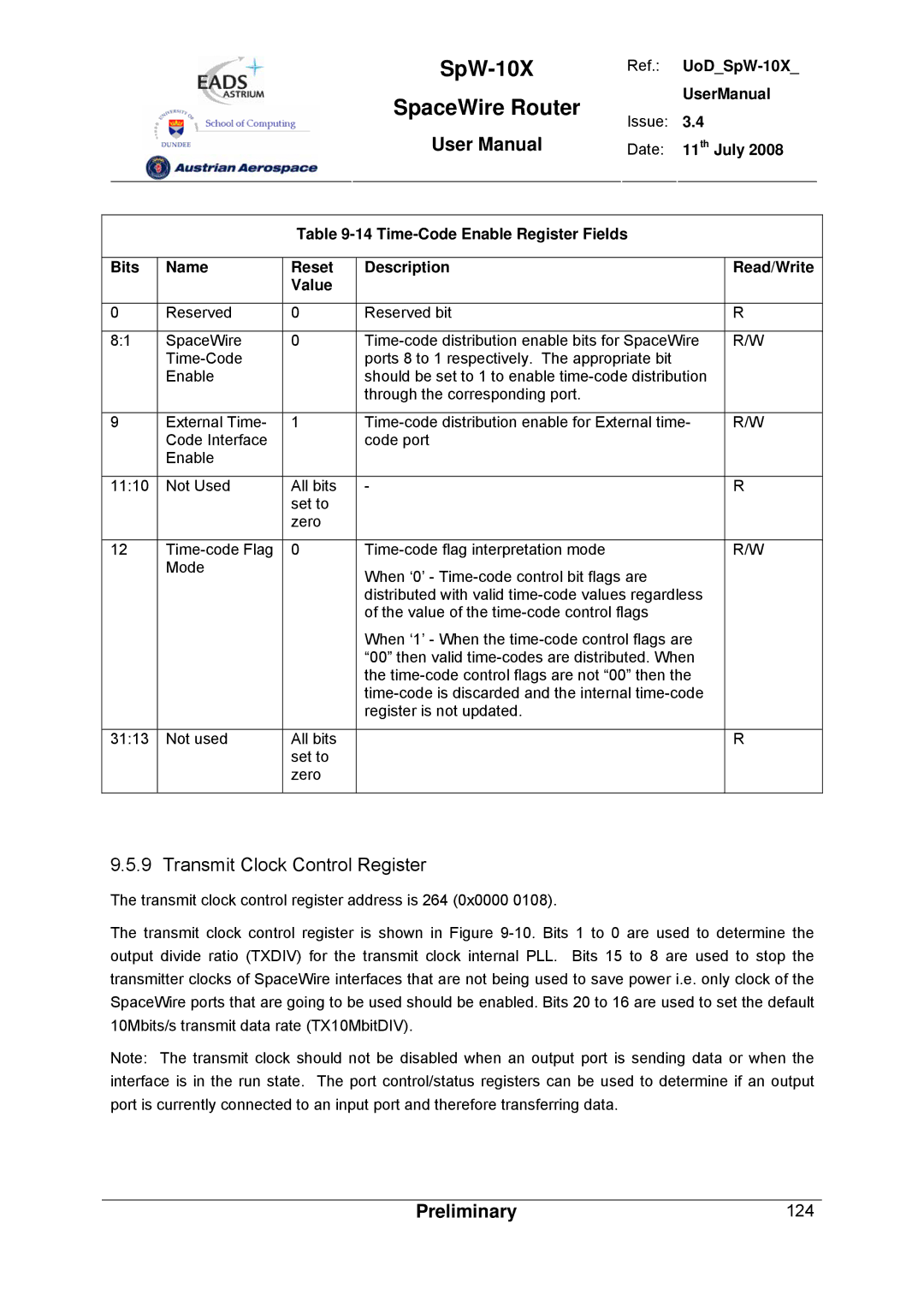
| Table |
|
|
| ||
|
|
|
|
|
|
|
| |
Bits | Name | Reset | Description |
|
| Read/Write |
| |
|
|
| Value |
|
|
|
|
|
|
|
|
|
|
|
|
| |
0 | Reserved | 0 | Reserved bit |
|
| R |
| |
|
|
|
|
|
| |||
8:1 | SpaceWire | 0 | R/W |
| ||||
|
|
| ports 8 to 1 respectively. The appropriate bit |
|
|
| ||
|
| Enable |
| should be set to 1 to enable |
|
| ||
|
|
|
| through the corresponding port. |
|
|
|
|
|
|
|
|
|
| |||
9 | External Time- | 1 | R/W |
| ||||
|
| Code Interface |
| code port |
|
|
|
|
|
| Enable |
|
|
|
|
|
|
|
|
|
|
|
|
|
| |
11:10 | Not Used | All bits | - |
|
| R |
| |
|
|
| set to |
|
|
|
|
|
|
|
| zero |
|
|
|
|
|
|
|
|
|
|
|
|
| |
12 | 0 |
|
| R/W |
| |||
|
| Mode |
| When ‘0’ - |
|
|
| |
|
|
|
|
|
|
| ||
|
|
|
| distributed with valid |
|
| ||
|
|
|
| of the value of the |
|
|
| |
|
|
|
| When ‘1’ - When the |
|
| ||
|
|
|
| “00” then valid |
|
| ||
|
|
|
| the |
|
| ||
|
|
|
|
|
| |||
|
|
|
| register is not updated. |
|
|
|
|
|
|
|
|
|
|
|
| |
31:13 | Not used | All bits |
|
|
| R |
| |
|
|
| set to |
|
|
|
|
|
|
|
| zero |
|
|
|
|
|
|
|
|
|
|
|
|
|
|
9.5.9 Transmit Clock Control Register
The transmit clock control register address is 264 (0x0000 0108).
The transmit clock control register is shown in Figure
Note: The transmit clock should not be disabled when an output port is sending data or when the interface is in the run state. The port control/status registers can be used to determine if an output port is currently connected to an input port and therefore transferring data.
Preliminary | 124 |