| Ref.: |
| |
SpaceWire Router |
| UserManual | |
Issue: | 3.4 | ||
User Manual | |||
Date: | 11th July 2008 | ||
|
|
|
9. REGISTER DEFINITIONS
This section describes the internal configuration registers of the
The following subsections contain register bit description tables which hold the following information:
•The bit numbers of each field
•A descriptive name for each field
•The reset value for each field
•A description of what the each field in the register is used for
•An indication of whether the field is readable and/or writeable by a configuration command.
The internal register size is 32 bits unless otherwise specified in the register description. There are 263 registers in the configuration port addresses. Registers that are shorter than
9.1 INTERNAL MEMORY MAP
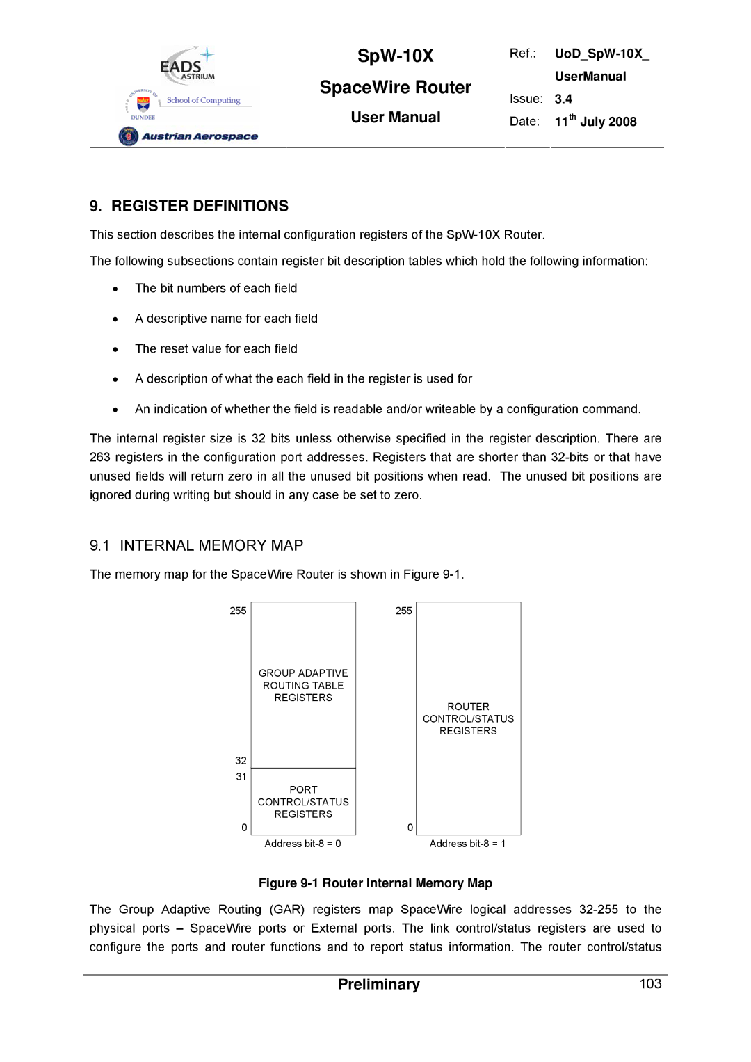
The memory map for the SpaceWire Router is shown in Figure 9-1.
255
32
31
0
GROUP ADAPTIVE ROUTING TABLE REGISTERS
PORT
CONTROL/STATUS
REGISTERS
Address
255
0
ROUTER
CONTROL/STATUS
REGISTERS
Address
Figure 9-1 Router Internal Memory Map
The Group Adaptive Routing (GAR) registers map SpaceWire logical addresses
Preliminary | 103 |
