| Ref.: |
| |
SpaceWire Router |
| UserManual | |
Issue: | 3.4 | ||
User Manual | |||
Date: | 11th July 2008 | ||
|
|
|
10. SWITCHING CHARACTERISTICS
10.1 CLOCK AND RESET TIMING PARAMETERS
The global clock and asynchronous reset timing parameters are listed below.
Table
Description | Symbol | Value | Units |
|
|
|
|
Clock period minimum value | TCL | 31.7(1) | ns, min |
|
| (TBC) |
|
|
|
|
|
Clock period maximum value | TCH | 35(2) | ns, max |
|
| (TBC) |
|
|
|
|
|
Clock minimum pulse width | TACLK | 5 | ns, min |
|
|
|
|
Clock input jitter | TCJITTER | +/- 2 | ns, max |
|
|
|
|
PLL lock time after reset | TPLLLOCK | 20 | µs, max |
|
|
|
|
Reset minimum pulse width | TARST | 5 | ns, min |
|
|
|
|
Reset end till operational | TRST2OP | 20 | ns, max |
|
|
|
|
(1)The PLL max. frequency is 200 MHz+TBD MHz.
(2)The PLL min. frequency is 100
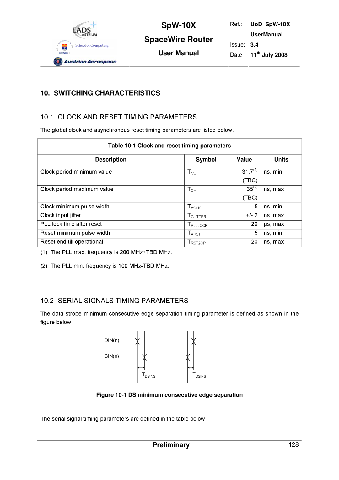
10.2 SERIAL SIGNALS TIMING PARAMETERS
The data strobe minimum consecutive edge separation timing parameter is defined as shown in the figure below.
DIN(n) |
|
SIN(n) |
|
TDSINS | TDSINS |
Figure 10-1 DS minimum consecutive edge separation
The serial signal timing parameters are defined in the table below.
Preliminary | 128 |