| Ref.: |
| |
SpaceWire Router |
| UserManual | |
Issue: | 3.4 | ||
User Manual | |||
Date: | 11th July 2008 | ||
|
|
|
Vdd | 3.3 V |
|
|
|
|
|
|
| |
2850 Ω | 2850 Ω | 20 kΩ |
| |
91 µA | 87 µA |
| 12 µA | 3.05 V |
|
|
|
| |
| 10 mV |
| RT =100 Ω |
|
|
|
| ||
|
|
| 99 µA 3.04 V | |
|
|
| ||
16 kΩ
![]() 190 µA
190 µA
+
‐
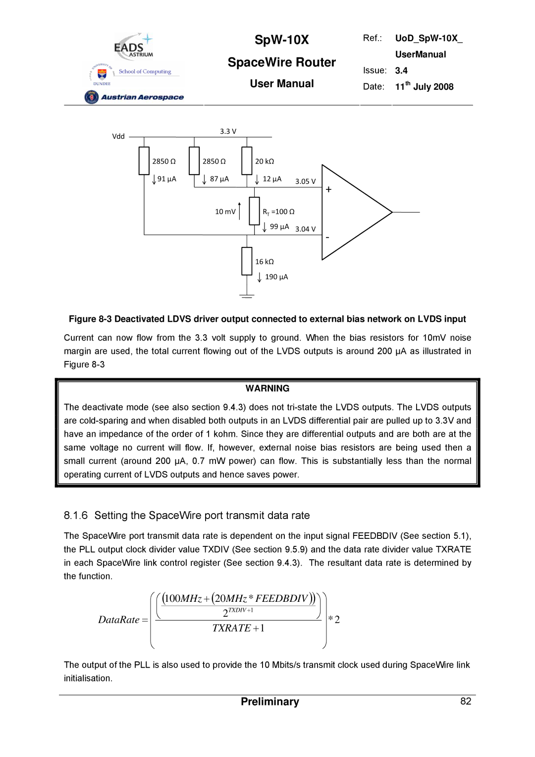
Figure 8-3 Deactivated LDVS driver output connected to external bias network on LVDS input
Current can now flow from the 3.3 volt supply to ground. When the bias resistors for 10mV noise margin are used, the total current flowing out of the LVDS outputs is around 200 µA as illustrated in Figure
WARNING
The deactivate mode (see also section 9.4.3) does not
8.1.6 Setting the SpaceWire port transmit data rate
The SpaceWire port transmit data rate is dependent on the input signal FEEDBDIV (See section 5.1), the PLL output clock divider value TXDIV (See section 9.5.9) and the data rate divider value TXRATE in each SpaceWire link control register (See section 9.4.3). The resultant data rate is determined by the function.
⎛ | ⎛ | (100MHz + (20MHz * FEEDBDIV ))⎞ ⎞ |
| ||
⎜ | ⎜ |
| ⎟ ⎟ |
| |
2TXDIV +1 |
| ||||
DataRate = ⎜ | ⎝ | ⎠ ⎟ | * 2 | ||
| TXRATE +1 |
| ⎟ | ||
⎜ |
|
|
| ||
⎜ |
|
|
| ⎟ |
|
⎝ |
|
|
| ⎠ |
|
The output of the PLL is also used to provide the 10 Mbits/s transmit clock used during SpaceWire link initialisation.
Preliminary | 82 |