| Ref.: |
| |
SpaceWire Router |
| UserManual | |
Issue: | 3.4 | ||
User Manual | |||
Date: | 11th July 2008 | ||
|
|
|
5.2.2 SpaceWire Input Fail Safe Resistors
If a SpaceWire input becomes disconnected then no current flows through the termination resistor. The differential voltage across this resistor is then zero. A small noise current, induced by electro- magnetic interference on PCB tracks or on any part of the SpaceWire cable still attached to the receiver, will cause a small differential voltage across the termination resistor. If this is positive the receiver output will be logic 1 and if it the noise current flows in the other direction, giving a negative differential voltage the receiver output will be logic 0. Just a small amount of noise is sufficient to cause the output of the LVDS receiver to transition from 0 to 1 and back continuously. This noise can sometime start a SpaceWire link erroneously.
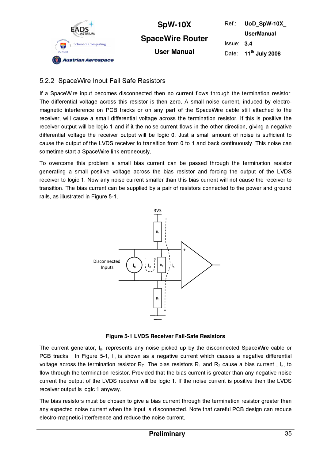
To overcome this problem a small bias current can be passed through the termination resistor generating a small positive voltage across the bias resistor and forcing the output of the LVDS receiver to logic 1. Now any noise current smaller than this bias current will not cause the receiver to transition. The bias current can be supplied by a pair of resistors connected to the power and ground rails, as illustrated in Figure
3V3
R1
+
Disconnected | In | In | RT | Ib |
Inputs |
‐
R2
Figure 5-1 LVDS Receiver Fail-Safe Resistors
The current generator, In, represents any noise picked up by the disconnected SpaceWire cable or PCB tracks. In Figure
The bias resistors must be chosen to give a bias current through the termination resistor greater than any expected noise current when the input is disconnected. Note that careful PCB design can reduce
Preliminary | 35 |