| Ref.: |
| |
SpaceWire Router |
| UserManual | |
Issue: | 3.4 | ||
User Manual | |||
Date: | 11th July 2008 | ||
|
|
|
|
|
|
|
| Return NULLs | Data Received | Disconnect | |||||
| Deactivated | Detected | ||||||||||
DOUT |
|
|
|
|
|
|
| Deactivated | ||||
|
|
|
|
|
|
|
|
|
|
|
| |
SOUT | Deactivated |
|
|
|
|
|
|
| Deactivated | |||
|
|
|
|
|
|
| ||||||
|
|
|
|
|
|
|
|
|
|
|
| |
|
| NULL received |
|
|
| DS reset | ||||||
|
| Activate output |
|
|
| Deactivate output | ||||||
|
|
| Connection made | Data Transfer | Disconnect | |||||||
|
|
|
|
|
|
|
|
|
|
|
|
|
DIN
SIN
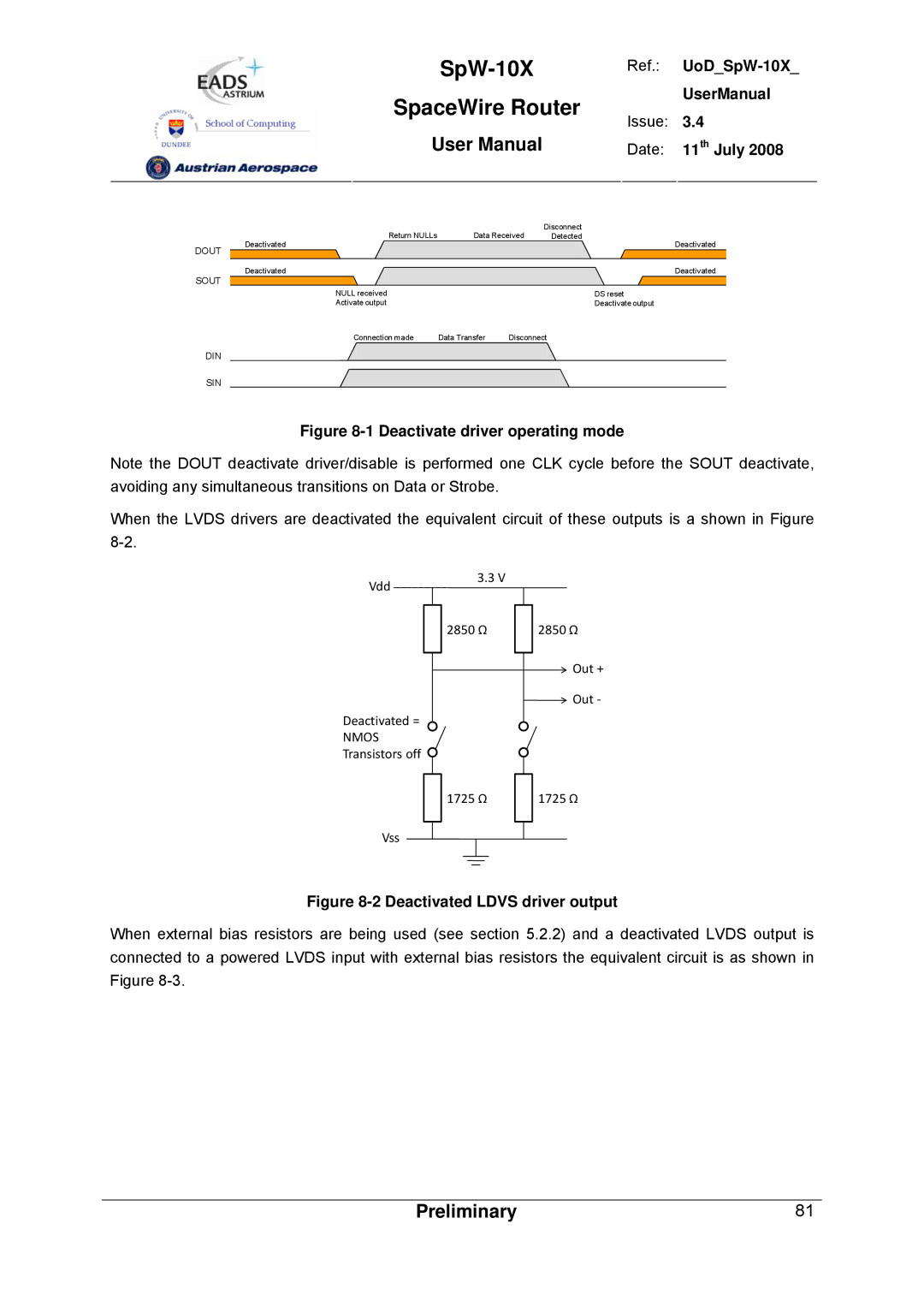
Figure 8-1 Deactivate driver operating mode
Note the DOUT deactivate driver/disable is performed one CLK cycle before the SOUT deactivate, avoiding any simultaneous transitions on Data or Strobe.
When the LVDS drivers are deactivated the equivalent circuit of these outputs is a shown in Figure
Vdd
3.3 V
2850 Ω | 2850 Ω |
Out +
![]() Out ‐
Out ‐
Deactivated =
NMOS
Transistors off ![]()
1725 Ω | 1725 Ω |
Vss
Figure 8-2 Deactivated LDVS driver output
When external bias resistors are being used (see section 5.2.2) and a deactivated LVDS output is connected to a powered LVDS input with external bias resistors the equivalent circuit is as shown in Figure
Preliminary | 81 |
