24AMX Switch Series Installer/User Guide
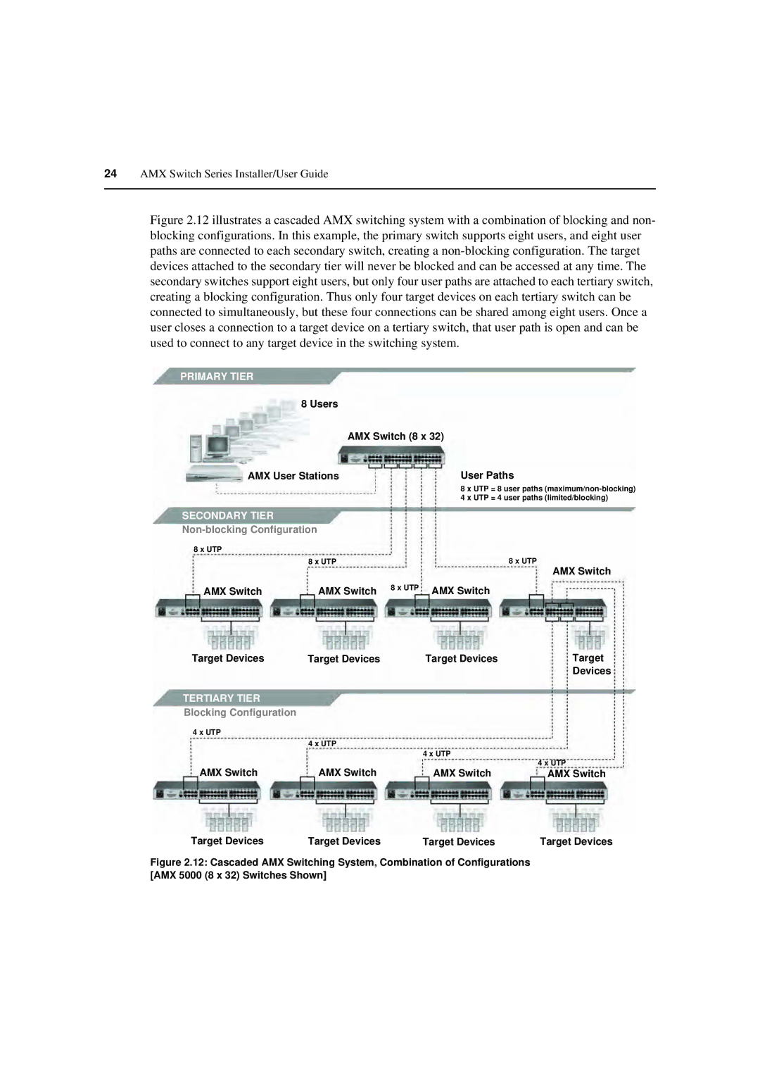
Figure 2.12 illustrates a cascaded AMX switching system with a combination of blocking and non- blocking configurations. In this example, the primary switch supports eight users, and eight user paths are connected to each secondary switch, creating a non-blocking configuration. The target devices attached to the secondary tier will never be blocked and can be accessed at any time. The secondary switches support eight users, but only four user paths are attached to each tertiary switch, creating a blocking configuration. Thus only four target devices on each tertiary switch can be connected to simultaneously, but these four connections can be shared among eight users. Once a user closes a connection to a target device on a tertiary switch, that user path is open and can be used to connect to any target device in the switching system.
PRIMARY TIER
8 Users
AMX Switch (8 x 32)
AMX User Stations
User Paths
8 x UTP = 8 user paths
SECONDARY TIER
Non-blocking Configuration
8 x UTP |
|
|
|
| 8 x UTP |
| 8 x UTP |
|
|
| AMX Switch |
AMX Switch | AMX Switch | 8 x UTP | AMX Switch |
|
Target Devices | Target Devices | Target Devices | Target | |
|
|
| Devices | |
TERTIARY TIER |
|
|
| |
Blocking Configuration |
|
|
| |
4 x UTP |
|
|
| |
| 4 x UTP | 4 x UTP |
| |
|
| 4 x UTP | ||
AMX Switch | AMX Switch | AMX Switch | ||
AMX Switch |
Target Devices | Target Devices | Target Devices | Target Devices |
