Example: Determining Pipe Size for Natural Gas
A generator has a 16Hp engine 60 feet from the supply. Determine the supply pipe size for Natural Gas fuel.
16 x 10,000 = 160,000 BTU's / per hour for proper operation. 160, 000
1, 096
+ 146cubicfeetperhour.
From Table 3‐6, a 60 foot run requires a minimum 1” pipe at full engine load.
Natural Gas Connections
The incoming pressure must be 11 inches water column (6 oz. pressure).
Table 3‐5 Natural Gas Flow Rate (Cubic Feet per Hour) per Pipe Length
Pipe |
|
|
|
|
| Iron Pipe Size |
|
|
|
|
| ||
Length |
|
|
|
|
|
|
|
|
|
|
|
|
|
1/ ″ | 3/ ″ | 1″ | 1- 1/ ″ | 1- 1/ ″ |
| 2″ |
| 2- 1/ ″ | 3″ | 4″ | 6″ | 8″ | |
(Feet) |
|
| |||||||||||
2 | 4 |
| 4 | 2 |
|
|
| 2 |
|
|
|
| |
15 | 73 | 165 | 332 | 722 | 1174 |
| 2386 |
| 3704 | 6253 | 13352 | 37229 |
|
30 | 50 | 115 | 232 | 515 | 818 |
| 1712 |
| 2646 | 4521 | 9331 | 26330 | 53728 |
45 | 41 | 95 | 191 | 418 | 673 |
| 1419 |
| 2213 | 3752 | 7600 | 22462 | 43867 |
60 | 37 | 83 | 166 | 366 | 587 |
| 1241 |
| 1924 | 3319 | 6542 | 18595 | 37999 |
75 |
| 74 | 149 | 332 | 524 |
| 1077 |
| 1684 | 2886 | 5772 | 16652 | 33959 |
90 |
| 67 | 137 | 298 | 433 |
| 962 |
| 1501 | 2597 | 5291 | 15200 | 31025 |
105 |
| 63 | 126 | 274 |
|
| 885 |
| 1376 | 2357 | 4906 | 14064 | 28715 |
120 |
|
| 115 | 260 | 404 |
| 827 |
| 1289 | 2213 | 4618 | 13160 | 26859 |
150 |
|
| 105 | 233 | 366 |
| 750 |
| 1174 | 2011 | 4185 | 11775 | 24050 |
180 |
|
| 96 | 216 | 337 |
| 693 |
| 1077 | 1876 | 3848 | 10736 | 21934 |
210 |
|
| 89 | 197 | 308 |
| 635 |
| 991 | 1712 | 3559 | 9937 | 20298 |
240 |
|
|
| 183 | 289 |
| 596 |
| 933 | 1616 | 3357 | 9235 | 18990 |
270 |
|
|
| 171 | 274 |
| 558 |
| 875 | 1520 | 3127 | 8658 | 17903 |
300 |
|
|
| 164 | 260 |
| 524 |
| 827 | 1433 | 2886 | 8177 | 16998 |
Note: Almost all operation problems are related to the installation techniques used. Do Not guess, be sure pipe size is adequate for required flow rate.
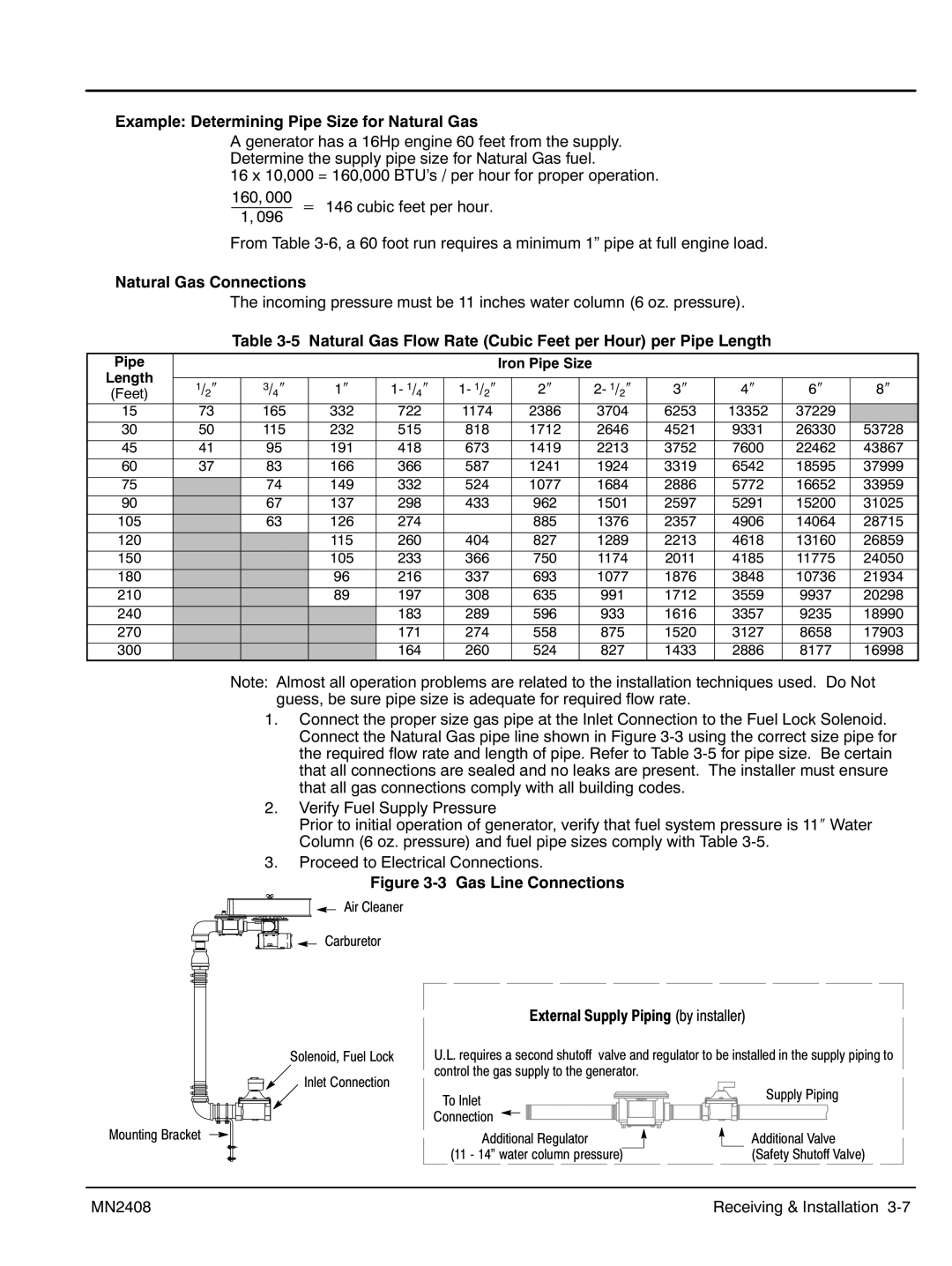
1.Connect the proper size gas pipe at the Inlet Connection to the Fuel Lock Solenoid. Connect the Natural Gas pipe line shown in Figure 3‐3 using the correct size pipe for the required flow rate and length of pipe. Refer to Table 3‐5 for pipe size. Be certain that all connections are sealed and no leaks are present. The installer must ensure that all gas connections comply with all building codes.
2.Verify Fuel Supply Pressure
Prior to initial operation of generator, verify that fuel system pressure is 11″ Water Column (6 oz. pressure) and fuel pipe sizes comply with Table 3‐5.
3.Proceed to Electrical Connections.
Figure 3‐3 Gas Line Connections
Air Cleaner
Carburetor
Solenoid, Fuel Lock
Inlet Connection
Mounting Bracket
External Supply Piping (by installer)
U.L. requires a second shutoff valve and regulator to be installed in the supply piping to control the gas supply to the generator.
To Inlet | Supply Piping |
| |
Connection |
|
Additional Regulator | Additional Valve |
(11 - 14” water column pressure) | (Safety Shutoff Valve) |
MN2408 | Receiving & Installation 3‐7 |