Digital Engine Controller Description EM0046A21 (MRS17) Continued
Operating Mode Press Mode A or " to scroll though the list of operating modes: Off, Manual and Automatic. The control mode is shown in the highlighted area at the top of the display, Figure 4‐9.
When the desired Control Mode is highlighted, press Start to begin operation. Press Stop to terminate operation.
OFF - Generator set operation is not allowed.
MAN - Press Start to manually start the generator set immediately. Press Stop to stop the generator set immediately.
AUT - Start and Stop buttons are ignored.
The binary input terminal conditions start and stop the generator set.
Display Menus Three display menus are available: Measurement, Adjustment and history.
Press the Page button repeatedly to display each menu. Use Y B and Enter keys to change and accept setpoint values or press the Page button to cancel changes.
Measurement Menu
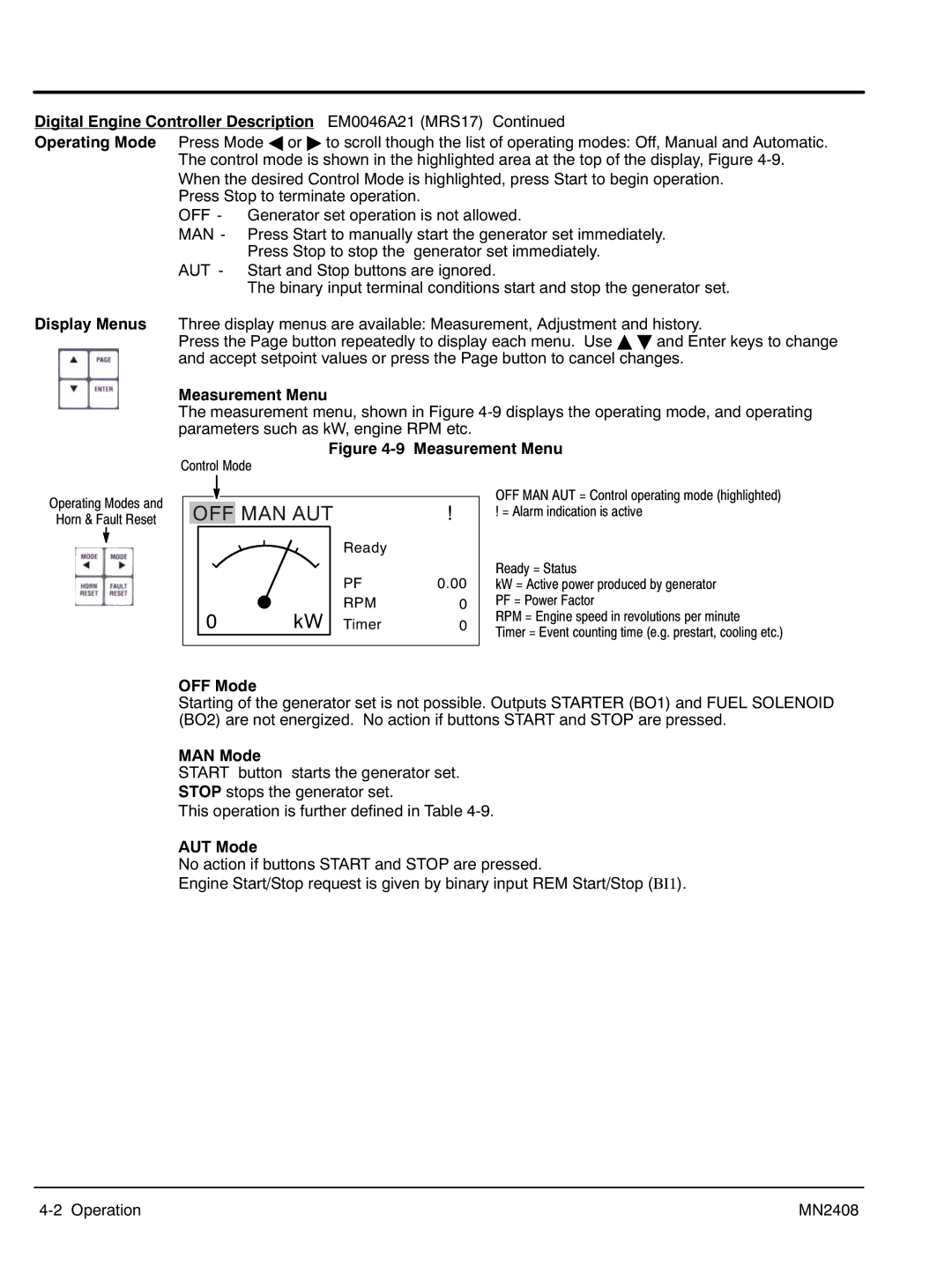
The measurement menu, shown in Figure 4‐9 displays the operating mode, and operating parameters such as kW, engine RPM etc.
Figure 4‐9 Measurement Menu
Control Mode
Operating Modes and
Horn & Fault Reset
|
|
|
|
|
|
|
| OFF | MAN AUT | ! | |||
|
|
|
|
| Ready |
|
|
|
|
|
|
| |
|
|
|
|
| PF | 0.00 |
|
| 0 |
| kW | RPM | 0 |
|
|
| Timer | 0 | ||
|
|
|
|
|
|
|
OFF MAN AUT = Control operating mode (highlighted) ! = Alarm indication is active
Ready = Status
kW = Active power produced by generator PF = Power Factor
RPM = Engine speed in revolutions per minute
Timer = Event counting time (e.g. prestart, cooling etc.)
OFF Mode
Starting of the generator set is not possible. Outputs STARTER (BO1) and FUEL SOLENOID (BO2) are not energized. No action if buttons START and STOP are pressed.
MAN Mode
START button starts the generator set.
STOP stops the generator set.
This operation is further defined in Table 4‐9.
AUT Mode
No action if buttons START and STOP are pressed.
Engine Start/Stop request is given by binary input REM Start/Stop (BI1).
4‐2 Operation | MN2408 |