Generator AC Metering The controller is in the display mode at all times except when in the programming mode. The display screens and menus may be selected by pressing the Enter or Exit keys to access Operating Status Display, Fault Display, Timer Countdown, Generator AC Metering or Programming Menus. The LCD display shows the status of the generator output:
Generator Average Output Display
Vavg Aavg Freq
000 000 000
Average Voltage | Displays the average generator voltage as follows: |
| |
|
Average Current
Frequency
Generator KVA Display
Displays the average generator current as follows:
Displays generator frequency in hertz (HZ). The frequency is displayed with a resolution of 1/10 of a hertz.
KVA
632.23
KVA | Displays the generator's total power output in |
Generator Phase Voltage Display (Line to Line)
Vab | Vbc | Vca |
600 | 600 | 600 |
Vab | Displays the generator's output voltage: |
| |
| |
Vbc | Displays the generator's output voltage: |
| |
| |
Vca | Displays the generator's output voltage: |
| |
|
Generator Phase/Neutral Voltage Display (Line to Neutral)
Van | Vbn | Vcn |
347 | 347 | 347 |
Note: | The generator's neutral must be connected to controller terminal |
| program menu must be selected as “Yes”. |
Van | Displays generator voltage Phase A to Neutral. |
Vbn | Displays generator voltage Phase B to Neutral. |
Vcn | Displays generator voltage Phase C to Neutral. |
Generator Phase Current Display
Amps a | b | c |
408 | 451 | 415 |
Amps a | Displays generator load current as follows: |
| |
| |
Amps b | Displays generator load current as follows: |
| |
| |
Amps c | Displays generator load current as follows: |
| |
|
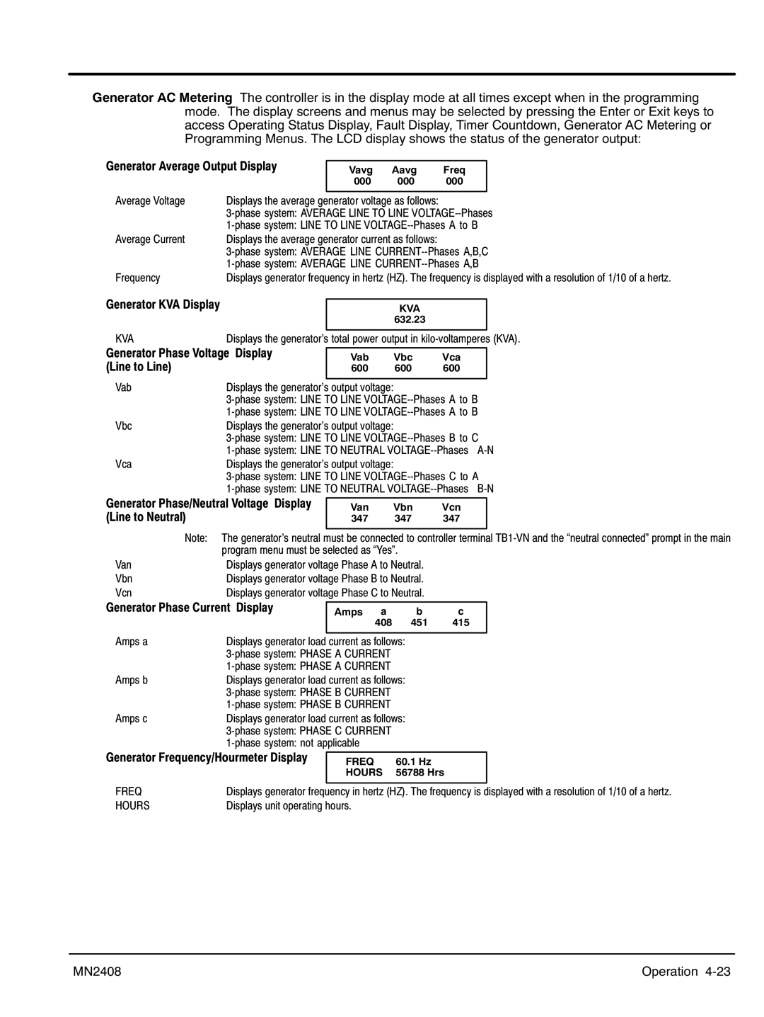
Generator Frequency/Hourmeter Display
FREQ | 60.1 Hz |
HOURS | 56788 Hrs |
FREQ | Displays generator frequency in hertz (HZ). The frequency is displayed with a resolution of 1/10 of a hertz. |
HOURS | Displays unit operating hours. |
MN2408 | Operation 4‐23 |