Section 4
Operation
Digital Engine Controller Description EM0046A21 (MRS17)
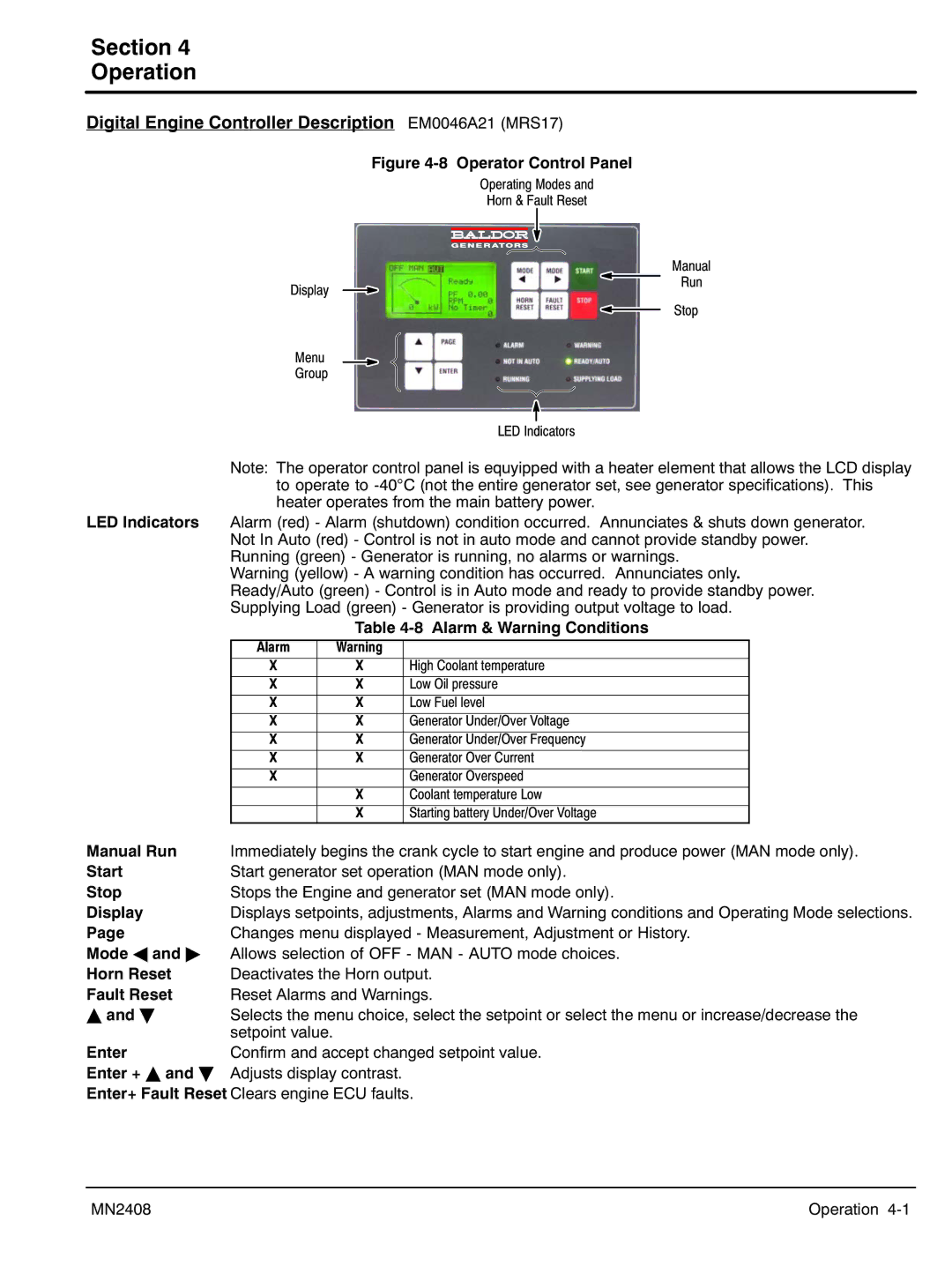
Figure 4‐8 Operator Control Panel
Operating Modes and
Horn & Fault Reset
Manual
Display
Run
Stop
Menu
Group
LED Indicators
Note: The operator control panel is equyipped with a heater element that allows the LCD display to operate to
LED Indicators Alarm (red) - Alarm (shutdown) condition occurred. Annunciates & shuts down generator. Not In Auto (red) - Control is not in auto mode and cannot provide standby power. Running (green) - Generator is running, no alarms or warnings.
Warning (yellow) - A warning condition has occurred. Annunciates only. Ready/Auto (green) - Control is in Auto mode and ready to provide standby power. Supplying Load (green) - Generator is providing output voltage to load.
Table 4‐8 Alarm & Warning Conditions
Alarm | Warning |
|
X | X | High Coolant temperature |
X | X | Low Oil pressure |
X | X | Low Fuel level |
X | X | Generator Under/Over Voltage |
X | X | Generator Under/Over Frequency |
X | X | Generator Over Current |
X |
| Generator Overspeed |
| X | Coolant temperature Low |
| X | Starting battery Under/Over Voltage |
Manual Run | Immediately begins the crank cycle to start engine and produce power (MAN mode only). |
Start | Start generator set operation (MAN mode only). |
Stop | Stops the Engine and generator set (MAN mode only). |
Display | Displays setpoints, adjustments, Alarms and Warning conditions and Operating Mode selections. |
Page | Changes menu displayed - Measurement, Adjustment or History. |
Mode A and " | Allows selection of OFF - MAN - AUTO mode choices. |
Horn Reset | Deactivates the Horn output. |
Fault Reset | Reset Alarms and Warnings. |
Y and B | Selects the menu choice, select the setpoint or select the menu or increase/decrease the |
| setpoint value. |
Enter | Confirm and accept changed setpoint value. |
Enter + Y and B | Adjusts display contrast. |
Enter+ Fault Reset Clears engine ECU faults.
MN2408 | Operation 4‐1 |