Analog Inputs Three analog inputs for resistive sensor 0 to 2400 ohms measuring are available on IL controller. Use LiteEdit software to modify configuration.
The Analog inputs values assignment (AI1 = Oil press, AI2 = Water temp, AI3 = Fuel level) is fix. It is possible to configure on each Analog input:
SReading from IL Analog inputs or from Engine Control Unit via CAN bus (J1939)
SSensor characteristics - from the list,
SValue dimension (e.g. psi - bars, °F - °C, % - l)
SNumber of decimal points (0, 1, 2, ...).
Note: Corresponding Analog input terminal is dead when reading is switched to ECU.
All values from ECU shall show ####, but no alarm is displayed when CAN communication is interrupted.
Warning and
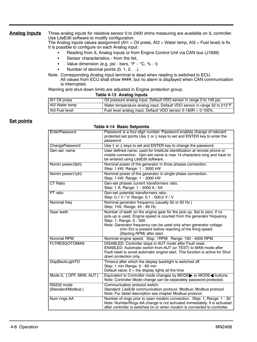
| Table 4‐13 Analog Inputs | |
AI1 Oil press |
| Oil pressure analog input. Default VDO sensor in range 0 to 145 psi. |
AI2 Water temp |
| Water temperature analog input. Default VDO sensor in range 32 to 212°F |
|
|
|
AI3 Fuel level |
| Fuel level analog input. Default VDO sensor |
Set points
Table 4‐14 Basic Setpoints | |
EnterPassword | Password is a |
| protected set points Use ⇑ or ⇓ keys to set and ENTER key to enter the |
| password. |
|
|
ChangePassword | Use ⇑ or ⇓ keys to set and ENTER key to change the password. |
User defined name, used for InteliLite identification at remote phone or | |
| mobile connection. |
| be entered using LiteEdit software. |
|
|
Nomin power(3ph) | Nominal power of the generator in three phases connection. |
| Step: 1 kW; Range: 1 - 3000 kW |
|
|
Nomin power(1ph) | Nominal power of the generator in |
| Step: 1 kW; Range: 1 - 3000 kW |
|
|
CT Ratio | |
| Step: 1 A; Range: 1 - 5000 A / 5A |
|
|
PT ratio | |
| Step: 0,1 V / V; Range: 0,1 - 500,0 V / V |
|
|
Nominal freq | Nominal generator frequency (usually 50 or 60 Hz ) |
| Step: 1Hz; Range: 45 - 65 Hz |
|
|
Gear teeth | Number of teeth on the engine gear for the |
| |
| Step: 1; Range: 0 - 500 |
| Note: Generator frequency can be used only when generator voltage |
| (min 5V) is present before reaching of the firing speed |
| (Starting RPM) after start. |
|
|
Nominal RPM | Nominal engine speed. Step: 1RPM; Range: 100 - 4000 RPM. |
FLTRESGOTOMAN | DISABLED: Controller stays in AUT mode after Fault reset . |
| ENABLED: Automatic switch from AUT (or TEST) to MAN mode after |
| Fault reset to avoid automatic engine start. This function is active for Shut |
| down protection only. |
|
|
DispBackLightTO | Timeout after which the display backlight is switched off. |
| Step: 1 min Range: 0 - 60 min |
| Default value: 0 = the display lights all the time |
|
|
Mode IL [ OFF, MAN, AUT ] | Equivalent to Controller mode changes by MODE" or MODEA buttons. |
| Note: Controller Mode change can be separately password protected. |
|
|
RS232 mode | Communication protocol switch. |
[Standard/Modbus ] | Standard: LiteEdit communication protocol. Modbus: Modbus protocol. |
| Note: For detail description see chapter Modbus protocol. |
|
|
Num rings AA | Number of rings prior to open modem connection. Step: 1; Range: 1 - 30 |
| Note: NumberRings AA change is not activated immediately. It is activated |
| after controller is switched on or when modem is connected to controller. |
4‐6 Operation | MN2408 |