Setting of switches AS1-5 to AS1-8
The function of switches
Table 4-2 AS1-5 to AS1-8 Description
Switch |
| Function | ON | OFF |
| Not Used |
|
| |
Offset Tuning | Automatic Offset Tuning is | Automatic Offset Tuning is not | ||
|
|
| active. | active. |
|
|
|
|
|
| Enable | Control is enabled | Control is disabled | |
|
|
| (Enable is active) | (Enable is not active) |
| OFF allows normal operation. |
| ||
|
| ON causes the motor to quickly decelerate to stop and maintain a constant | ||
|
| position (in current or velocity modes). (Time to max velocity = 0 with the Hold | ||
|
| function.) |
|
|
Offset Tuning | OFF allows normal operation. |
| ||
|
| ON causes Offset Tuning to automatically start the next time Enable is changed | ||
|
| from ON to OFF. The purpose of Offset Tuning is to remove DC offset voltages (on | ||
|
| the command input | ||
|
| 0VDC at the command input. Leave this switch OFF when not in use. See Figure | ||
|
|
| ||
Enable |
| OFF disables the control and the motor coasts to a stop. | ||
ON allows normal operation.
Note:
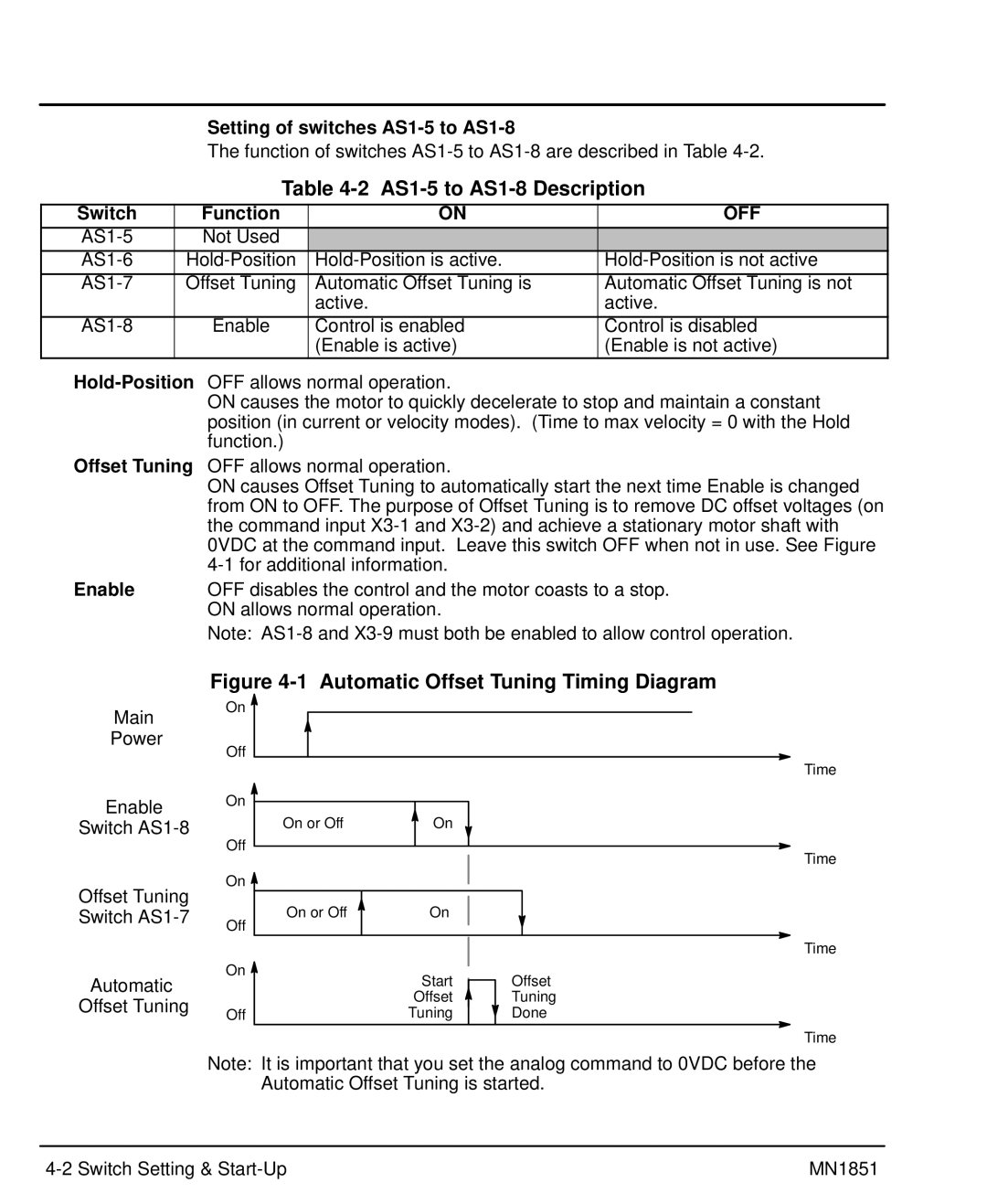
Figure 4-1 Automatic Offset Tuning Timing Diagram
Main
Power
Enable
Switch
Offset Tuning Switch
Automatic
Offset Tuning
On |
|
|
Off |
|
|
|
| Time |
On |
|
|
On or Off | On |
|
Off |
| Time |
|
| |
On |
|
|
On or Off | On |
|
Off |
|
|
|
| Time |
On | Start | Offset |
| ||
| Offset | Tuning |
Off | Tuning | Done |
|
| Time |
Note: It is important that you set the analog command to 0VDC before the Automatic Offset Tuning is started.
MN1851 |