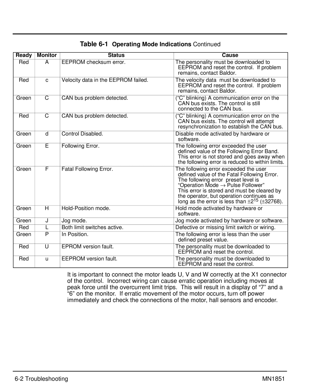
Table 6-1 Operating Mode Indications Continued
Ready | Monitor | Status | Cause | |
Red | A | EEPROM checksum error. | The personality must be downloaded to | |
|
|
| EEPROM and reset the control. If problem | |
|
|
| remains, contact Baldor. | |
|
|
|
| |
Red | c | Velocity data in the EEPROM failed. | The velocity data must be downloaded to | |
|
|
| EEPROM and reset the control. If problem | |
|
|
| remains, contact Baldor. | |
|
|
|
| |
Green | C | CAN bus problem detected. | (“C” blinking) A communication error on the | |
|
|
| CAN bus exists. The control is still | |
|
|
| connected to the CAN bus. | |
|
|
|
| |
Red | C | CAN bus problem detected. | (“C” blinking) A communication error on the | |
|
|
| CAN bus exists. The control will attempt | |
|
|
| resynchronization to establish the CAN bus. | |
|
|
|
| |
Green | d | Control Disabled. | Disable mode activated by hardware or | |
|
|
| software. |
|
Green | E | Following Error. | The following error exceeded the user | |
|
|
| defined value of the Following Error Band. | |
|
|
| This error is not stored and goes away when | |
|
|
| the following error is reduced to within limits. | |
Green | F | Fatal Following Error. | The following error exceeded the user | |
|
|
| defined value of the Fatal Following Error. | |
|
|
| The following error | preset level is |
|
|
| “Operation Mode → | Pulse Follower” |
|
|
| This error is stored and must be cleared by | |
|
|
| the operator, but operation continues as | |
|
|
| long as the error is less than ± 215 (± 32768). | |
Green | H | Hold mode activated by hardware or | ||
|
|
| software. |
|
Green | J | Jog mode. | Jog mode activated by hardware or software. | |
Red | L | Both limit switches active. | Defective or missing limit switch or wiring. | |
Green | P | In Position. | The following error is less than the user | |
|
|
| defined preset value. | |
Red | U | EPROM version fault. | The personality must be downloaded to | |
|
|
| EEPROM and reset the control. | |
Red | u | EEPROM version fault. | The personality must be downloaded to | |
|
|
| EEPROM and reset the control. | |
It is important to connect the motor leads U, V and W correctly at the X1 connector of the control. Incorrect wiring can cause erratic operation including moves at peak force until the overcurrent limit trips. This will result in a display of “7” and a “6” on the monitor. If erratic movement of the motor occurs, turn off power immediately and check the connections of the motor, hall sensors and encoder.
MN1851 |