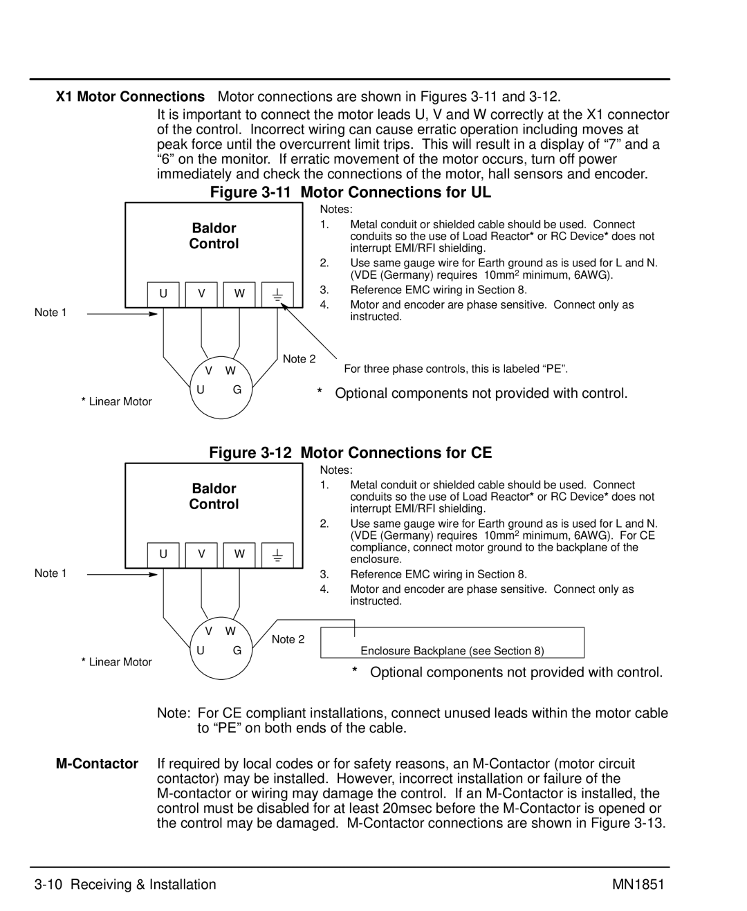
X1 Motor Connections Motor connections are shown in Figures
It is important to connect the motor leads U, V and W correctly at the X1 connector of the control. Incorrect wiring can cause erratic operation including moves at peak force until the overcurrent limit trips. This will result in a display of “7” and a “6” on the monitor. If erratic movement of the motor occurs, turn off power immediately and check the connections of the motor, hall sensors and encoder.
Figure 3-11 Motor Connections for UL
| Notes: |
Baldor | 1. Metal conduit or shielded cable should be used. Connect |
Control | conduits so the use of Load Reactor* or RC Device* does not |
interrupt EMI/RFI shielding. |
2.Use same gauge wire for Earth ground as is used for L and N. (VDE (Germany) requires 10mm2 minimum, 6AWG).
|
|
|
| U |
| V |
| W |
|
|
|
|
| 3. | Reference EMC wiring in Section 8. | ||||
|
|
|
|
|
|
|
|
|
|
| |||||||||
Note 1 |
|
|
|
|
|
|
|
|
|
|
|
|
|
|
|
|
| 4. | Motor and encoder are phase sensitive. Connect only as |
|
|
|
|
|
|
|
|
|
|
|
|
|
|
|
|
| |||
|
|
|
|
|
|
|
|
|
|
|
|
|
|
|
|
|
|
| instructed. |
|
|
|
|
|
|
|
|
|
|
|
|
|
|
|
| Note 2 | For three phase controls, this is labeled “PE”. | ||
|
|
|
|
|
|
|
| V |
| W |
|
|
|
| |||||
|
|
|
|
|
|
|
|
| |||||||||||
|
|
|
|
|
|
|
|
|
|
|
|
|
|
|
| ||||
* Linear Motor |
| U |
| G | * | Optional components not provided with control. | |||||||||||||
|
|
|
|
|
|
|
|
|
|
|
|
|
| ||||||
Figure 3-12 Motor Connections for CE
| Notes: |
Baldor | 1. Metal conduit or shielded cable should be used. Connect |
Control | conduits so the use of Load Reactor* or RC Device* does not |
interrupt EMI/RFI shielding. |
2.Use same gauge wire for Earth ground as is used for L and N.
|
|
|
|
|
|
|
|
|
|
|
|
|
|
|
| (VDE (Germany) requires 10mm2 minimum, 6AWG). For CE |
|
|
|
|
|
|
|
|
|
|
|
|
|
|
|
| compliance, connect motor ground to the backplane of the |
|
|
|
| U |
| V |
| W |
|
|
|
|
|
|
| |
Note 1 |
|
|
|
|
|
|
|
|
|
|
|
|
|
|
| enclosure. |
|
|
|
|
|
|
|
|
|
|
|
|
|
|
| ||
|
|
|
|
|
|
|
|
|
|
|
|
|
|
| 3. Reference EMC wiring in Section 8. | |
|
|
|
|
|
|
|
|
|
|
|
|
|
|
| ||
|
|
|
|
|
|
|
|
|
|
|
|
|
|
|
4.Motor and encoder are phase sensitive. Connect only as instructed.
V | W |
|
|
| |
Note 2 |
| ||||
U | G | Enclosure Backplane (see Section 8) | |||
|
| ||||
*Linear Motor
* Optional components not provided with control.
Note: For CE compliant installations, connect unused leads within the motor cable to “PE” on both ends of the cable.
MN1851 |
