Lin+Drive Servo Control
Table of Contents
Ii Table of Contents MN1851
Minimum system requirements
Appendix B
24VDC Logic Power Input
Appendix a
Iv Table of Contents MN1851
CE Compliance
Limited Warranty
Section General Information
Could result in damage to property
Product Notice Intended use
Could result in injury or death
General Information MN1851
Do not apply AC power before you ensure that grounds are
Do not touch any circuit board, power device or electrical
Connection before you first ensure that power has been
Voltages that are conducted to its power input terminals.
General Information MN1851
Section Product Overview
Control Outputs
Encoder Output
Section Receiving and Installation
Mechanical Installation
GND
Receiving & Installation MN1851
Control
Recommended System Grounding 1 phase for UL
Recommended System Grounding 1 phase for CE
Input Power Conditioning
System Grounding Ungrounded Distribution System
Breaker
Wire Size for units without Power Supply
X1 Power Connections
Mm2
Baldor Control
Components not provided with Control
Baldor
Baldor Option S Option P Control Regen Resistor
Earth
Breaker
Baldor Option P Control
� Important
LPxAxxxx-xxx3 only
To use an M4 bolt 12mm in length
Holes in the top and bottom
Enclosure are for cable clamps. Be sure
Longer bolts may short circuit
11 Motor Connections for UL
12 Motor Connections for CE
13 Optional M-Contactor Connections
Single Ended Connection Differential Connection
Control Input Wiring
X3 Control Inputs & Digital I/O Connections
X3 Digital Inputs Opto Isolated Inputs uses Cref
Opto Input Signal Conditions
Signal Name Opto Input Signal Definition
Process Duration
Time Required Duration
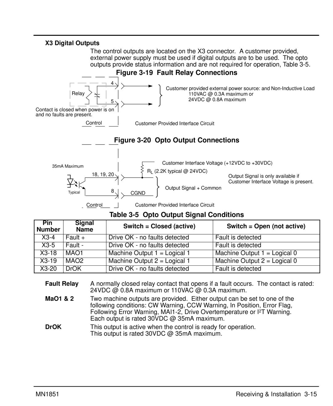
X3 Digital Outputs
Opto Output Signal Conditions
Fault Relay
MaO1
Control TXD
X6 RS232 / 485 Connections
Null Modem Cable Connections
Computer
RS485
What is a termination resistor?
Where are these resistors placed?
How many resistors should my system have?
TX+ RX+ Dgnd
= Twisted Pair
TX+ Dgnd GND
TX+ RX+ Dgnd GND
X7 Encoder Output
Buffered Encoder Output at X7 Connector
X7 Pin Signal Name
Reserved
X9 Encoder and Hall Feedback LPxAxxxx-Exxx
Control Address Setting
Section Switch Setting and Start-Up
Switch AS1 Settings
Address Setting, AS1-1 to AS1-4 for Multi-Drop Applications
Offset Tuning
Setting of switches AS1-5 to AS1-8
Switch Function
AS1-5 to AS1-8 Description
Power On Checks
Start-Up Procedure
Power Off Checks
Procedure
Switch Setting & Start-Up MN1851
Section Operation
Installing Software on your PC
Host Communications Setup
Windows
Windows NT
Using The Setup Wizard
Flowchart of the Setup Wizard
Operation MN1851
Page
There are 7 parts to the setup procedure Motor
Motor parameters. Click Download when finished
Encoder Feedback
Encoder Feedback
Encoder Feedback Motor pitch mm 60.96
Lmcf All Micron Counts / meter Counts / mm
Operating Mode Selection Screen
Operating Mode
Current Parameter
MN1851 Operation
Software Triggered
MAI4 MAI3 MAI2 MAI1
Index channel, Capture and Actual Position
Procedure to define home position
Home
Set this value. Click Download when finished
Drift
File
Setup
Main Menu Choice Descriptions
Edit
Functions
Tuning
Watch
Motion
PLC Program Menu
Help
Meters/second
Velocity Parameters RPM m/s
Linear Motor
MN1851 Troubleshooting
Section Troubleshooting
1Operating Mode Indications
Overview
Long as the error is less than ± 215 ±
Section Specifications & Product Data
Identification
+0 to 40. Above 40 C, derate the continuous and peak
Specifications
To 3300 feet 1000 meters. Derate the continuous
Output current by 2.5% per C above 40 C. Maximum
Peak output current by 1.1% for each 330 feet
Description Unit
Specifications & Product Data MN1851
24VDC Logic Power Input Option LPxAxxxx-xxx3 only
24VDC Logic Power Input Option LP4Axxxx-xxx3 only
Velocity Control
Encoder Input Feedback
Regeneration
Clearance Requirements all sizes 0.06″ 15mm top and bottom
Dimensions
Size A, B and C
CE Declaration of Conformity
Wiring of Shielded Screened Cables
Section CE Guidelines
EMC Conformity and CE Marking
Grounding Earth
EMC Wiring Technique
CE Guidelines MN1851
EMC Installation Instructions
Cable Screens Grounding
Encoder Input Cable Grounding
Input Signal Cable Grounding
Simulated Encoder Output Cable Grounding
To Controller
Mating Connector by connector number for spare parts
Section Accessories and Options
Connectors
Cables
Depth = F
AC Filter Dimensions
Accessories & Options MN1851
Fo r
Regeneration Resistor
Package
Accessories & Options MN1851
General Tuning Rules
Appendix a Manual Tuning
Tools are available to make tuning easier, such as
Manual Tuning
Manual Tuning MN1851
There are 7 parts to the setup procedure
Parameters. Click Download when finished
Motor
15240 000,000 10,000,000
Figure A-13 Current Parameter Screen
Figure A-14 Velocity Parameter Screen Drift
Figure A-15 Drift Parameter Screen
Figure A-16 Select Manual Tuning
Figure A-17 Inertia and Load Response Examples
Tracking factor
Figure A-18 PI Compensation Menu
Page
Graphic Screen
Plotting of Move
Control Window
Jog Block
Syntax General structure of the Ascii command
Appendix B Command Set
Lin Ascii Command Set General
MN1851 Command Set B-1
Encoder
Pulses/rev Resolution
Parameters and Units
Input Buffer Overflow command line exceeded 80 char
Start-up with Terminal Communication and Command Examples
Execution Error invalid command
Control Design Failure invalid control design
Basic System Parameters Motor Parameters MTR. prefixed
General Settings System Constants
Command Set MN1851
Drive Parameters typical DRV. prefixed
MN1851 Command Set B-5
Software Limit Switches Parameters
Variables None Software Limit Switches Methods
Command Description Units Range Default E2 / Par. set
PLC.LINE
PLC Parameters
Variables None PLC Methods
Relay
Digital Interface Parameters
MN1851 Command Set B-7
OCI Interface Parameters
Analog Interface Parameters
System Variables General Variables
Queries / modifications of Fault Listing Variables
X1 Possible Faults X1 Fault Display Description
Methods
Communication Settings Parameter
MN1851 Command Set B-9
Variable
Data Record REC. prefixed Variable
Queries of System Variables, Status, Faults Single Values
Data Record REC. prefixed Parameters
Eeprom related
Operation Mode Control Normal Modes Parameters
Memory related methods Queries / modifications RAM related
Normal Modes Variables
Current mode Methods
Sys.mod Current mode Parameters
Current mode Variables
Query for actual current command
Velocity mode Methods
Sys.mod 1 & Sys.mod Velocity mode Parameters
Velocity mode Variables
MN1851 Command Set B-13
JOG.TYPE
Jog Parameters
JOG.TIME
JOG.VEL
Variables
MN1851 Command Set B-15
Position Controller Position Controller Parameters
HW.PLC
HW.GRFX
HW.GRSH
HW.RES
Baldor Electric Company
Baldor Electric Company MN1851 10/00 C&J
Lin+Drive Servo Control MN1851