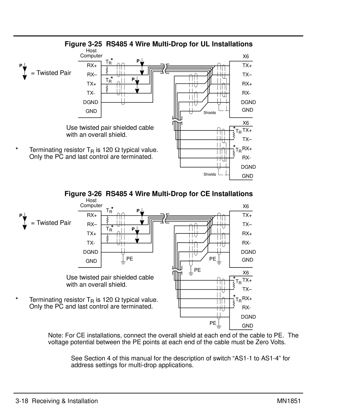
Figure 3-25 RS485 4 Wire Multi-Drop for UL Installations
| Host |
|
| Computer |
|
P | TR* | P |
RX+ |
| |
= Twisted Pair | RX– |
|
| TR* | P |
| TX+ |
|
| TX- |
|
| DGND |
|
| GND |
|
Use twisted pair shielded cable with an overall shield.
*Terminating resistor TR is 120 W typical value. Only the PC and last control are terminated.
X6
TX+
TX–
RX+
RX-
| DGND | |
Shields |
| GND |
|
| |
*T |
| X6 |
R | TX+ | |
|
| |
|
| TX– |
*T | R | RX+ |
|
| |
|
| RX- |
| DGND | |
Shields |
| GND |
|
| |
Figure 3-26 RS485 4 Wire Multi-Drop for CE Installations
| Host |
|
| Computer |
|
P | TR* | P |
RX+ |
| |
= Twisted Pair | RX– |
|
| TR* | P |
| TX+ |
|
| TX- |
|
| DGND |
|
| GND | PE |
|
|
Use twisted pair shielded cable with an overall shield.
*Terminating resistor TR is 120 W typical value. Only the PC and last control are terminated.
X6
TX+
TX–
RX+
RX-
| DGND | |
PE |
| GND |
PE |
| X6 |
*T |
| |
R | TX+ | |
|
| |
|
| TX– |
*T | R | RX+ |
|
| |
|
| RX- |
| DGND | |
PE |
| GND |
|
| |
Note: For CE installations, connect the overall shield at each end of the cable to PE. The voltage potential between the PE points at each end of the cable must be Zero Volts.
See Section 4 of this manual for the description of switch
MN1851 |